




Understanding Surge Voltage Testing with LISUN Baker Surge Tester for Motor and Coil Reliability
1. Surge Voltage Phenomena and Their Impact on Winding Insulation Systems
The operational integrity of inductive components—specifically motor windings, transformer coils, and solenoid assemblies—is critically dependent on the dielectric strength of their insulation systems. Transient overvoltages, commonly termed surges, represent high-energy, short-duration disturbances that can exceed the rated voltage by several orders of magnitude. These events originate from atmospheric lightning strikes, switching operations in power distribution networks, or the regenerative braking cycles in variable frequency drives (VFDs). In environments where power quality is inconsistent, such as those found in industrial equipment, rail transit systems, and spacecraft power conditioning units, the cumulative stress from repetitive surges accelerates partial discharge activity and eventual turn-to-turn, phase-to-phase, or phase-to-ground insulation failure.
Standardized surge testing, as prescribed by international norms including IEC 61000-4-5, is therefore indispensable for qualifying the robustness of a motor or coil prior to deployment. The testing methodology involves applying a defined voltage impulse with a specific rise time and decay duration—typically 1.2/50 µs for voltage waveshape and 8/20 µs for current waveshape—to simulate the most severe transient conditions encountered in the field. Without such validation, end products across lighting fixtures, household appliances, and medical devices risk premature failure, resulting in costly recalls and safety hazards.
2. Principle of Turn-to-Turn Surge Testing and Winding Diagnostics
Surge testing for coils and motors relies on the principle of resonant wave comparison. When a steep-fronted surge voltage is applied to a winding, the winding’s distributed inductance and capacitance form a complex LC network that oscillates at its natural frequency. A healthy winding exhibits a consistent, damped sinusoidal waveform with a characteristic period and amplitude envelope. However, incipient insulation defects—such as a shorted turn or weakened dielectric—alter the winding’s effective inductance or capacitance, thereby shifting the resonant frequency, damping factor, and zero-crossing pattern.
The LISUN Baker Surge Tester captures this oscillatory waveform and compares it against a stored reference from a known-good winding. The difference between the two waveforms, quantified as the error area ratio (EAR) or deviation percentage, provides a direct measure of insulation degradation. This technique is far more sensitive than traditional hi-pot or insulation resistance measurements, as it detects turn-to-turn faults that do not yet manifest as a low-resistance path to ground. For applications in high-reliability sectors such as automobile industry electric drivetrains and information technology equipment power supplies, this diagnostic capability is paramount for preventing in-field malfunctions.
3. The LISUN SG61000-5 서지 발생기: Core Specifications and Architecture
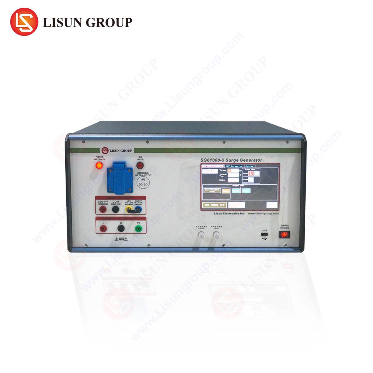
Central to the execution of these rigorous tests is the LISUN SG61000-5 Surge Generator. This instrument is engineered to produce the precise voltage and current waveforms mandated by IEC 61000-4-5 while offering the flexibility required for evaluating diverse inductive loads. The generator serves dual roles: as a standalone surge simulator for component-level testing and as an integrated winding analyzer when coupled with the Baker tester’s measurement circuitry.
Key technical specifications of the SG61000-5 include:
| 매개변수 | 사양 |
|---|---|
| 출력 전압 범위 | 0.2 kV to 6.6 kV (10 kV optional) |
| Voltage Waveshape (Open Circuit) | 1.2/50 µs (±10% rise, ±20% decay) |
| Current Waveshape (Short Circuit) | 8/20 µs (±10% rise, ±20% decay) |
| 극성 | Positive, Negative, or Alternating |
| Phase Angle Control | 0° to 360° (1° resolution) |
| Pulse Repetition Rate | Max 1 pulse per 5 seconds |
| 출력 임피던스 | 2 Ω (per IEC 61000-4-5) |
| 커플링/디커플링 네트워크(CDN) | Built-in, configurable for AC/DC lines |
| Safety Compliance | CE, EMC, LVD certified |
The instrument utilizes a high-voltage DC charging supply, a storage capacitor bank, and a wave-shaping network consisting of precision inductors and resistors controlled via solid-state switching. This architecture ensures repeatable surge characteristics across the entire voltage range, essential for generating statistically valid data during qualification testing.
4. Operational Workflow for Motor and Coil Reliability Assessment
The testing procedure employing the SG61000-5 for winding diagnostics follows a structured protocol. Initially, the operator configures the test voltage level based on the coil’s rated insulation class. For example, a low-voltage electrical appliance relay operating at 24 VDC might be tested at 500 V to 1 kV, whereas a 480 VAC industrial motor may require levels up to 5 kV per IEC 60034-18-41.
The workflow proceeds as follows:
- Isolation and Disconnection: The device under test (DUT) must be electrically isolated from other circuitry to prevent damage to sensitive components such as microcontrollers in intelligent equipment or communication transmission modules.
- Reference Acquisition: A known-good winding of identical construction is tested first, and its surge waveform envelope is stored as a baseline.
- Surge Application: The SG61000-5 injects a sequence of positive and negative surges (typically 3 to 5 pulses per polarity) into the winding terminals.
- Waveform Capture and Comparison: The Baker tester digitizes the resulting oscillatory waveform over a time window of 100 µs to 500 µs, then overlays it with the reference. The algorithm computes the area of discrepancy, flagging any deviation exceeding a user-defined threshold—commonly 10% for pass/fail criteria.
- Diagnostic Interpretation: A shift in resonant frequency indicates inductance change (turn short); increased damping suggests higher resistive losses (moisture ingress or carbonized paths); waveform distortion points to complex partial breakdown.
This method is applicable not only to rotating machinery but also to solenoids in power tools, valves in medical devices, and inductors in audio-video equipment power stages.
5. Application Sectors and Case-Specific Surge Considerations
The versatility of the SG61000-5 extends across a broad spectrum of industries, each with unique surge susceptibility profiles.
- Lighting Fixtures: LED drivers and ballast windings are exposed to surges from branch circuit switching. Testing per IEC 61000-4-5 at levels up to 2 kV (line-to-line) and 4 kV (line-to-ground) ensures compliance with EN 55015.
- 산업 장비: Variable frequency drives in conveyor systems and robotic arms require surge withstand capabilities of 4 kV to 6 kV. The SG61000-5’s phase angle control allows synchronization with mains zero-crossings to simulate worst-case commutation events.
- Household Appliances: Washing machine motors and compressor coils must endure surges from nearby appliance switching. Testing at 1 kV differential mode and 2 kV common mode is standard for IEC 60335-1 compliance.
- 의료기기: Defibrillators, infusion pumps, and MRI gradient coils demand ultra-reliable insulation. Surge voltages up to 6 kV are applied to verify double or reinforced insulation as per IEC 60601-1-2.
- Intelligent Equipment: Smart grid meters and IoT automation controllers incorporate sensitive power line communication circuits. Surge testing at 2 kV to 4 kV validates that surge arrestors and common-mode chokes function correctly.
- Communication Transmission: Base station power supplies and signal repeaters must survive lightning-induced surges (10 kV). The SG61000-5’s 10 kV extension option is critical for these applications.
- Audio-Video Equipment: Studio amplifiers and commercial projectors often operate in environments with poor grounding. Surge testing at 1 kV to 2 kV ensures no audible pop or device lockup occurs.
- Low-Voltage Electrical Appliances: Programmable thermostats and circuit breakers require verification of internal transformer winding integrity against surges of 0.5 kV to 1.5 kV.
- Power Tools: Brushless DC motor windings in saws and drills are compact and highly stressed. Turn-to-turn surge testing at 1 kV to 2 kV identifies manufacturing defects like enamel pinholes.
- Power Equipment: Distribution transformers and high-voltage switchgear require surge tests up to 10 kV per late-breaking standards (e.g., IEEE C57.12.00). The SG61000-5 with HV option fulfills this.
- Information Technology Equipment: Server power supplies and UPS inverters are tested per IEC 62040-2 at 2 kV. The Baker surge tester detects winding asymmetry that could cause core saturation.
- Rail Transit: Traction motor coils in electric locomotives experience repetitive surges from pantograph arcing. Testing at 6 kV with alternating polarity mirrors real-world conditions.
- Spacecraft: Satellite reaction wheel motors must survive surges during power bus switching. Testing in vacuum conditions (simulated) requires precise waveform control, a strength of the SG61000-5.
- Automobile Industry: WLTP and ISO 21498 compliance for EV traction motor stators demands surge testing up to 4 kV. The Baker tester provides gradation data for statistical process control.
- Electronic Components: Power inductors and common-mode chokes for DC-DC converters are tested at 1 kV to verify inter-winding insulation according to AEC-Q200.
- Instrumentation: Calibration-grade transformers in measurement apparatus require negligible error area ratio (<5%) after surge exposure.
6. Competitive Advantages of the LISUN SG61000-5 in Surge Testing
While multiple surge generators exist in the market, the SG61000-5 presents distinct technical and operational advantages tailored for motor and coil reliability.
Integrated CDN and Baker Functionality: Unlike many generators that require separate coupling/decoupling networks (CDNs) for AC or DC testing, the SG61000-5 incorporates a switchable CDN internal to the chassis. This reduces external cabling and parasitic inductance, ensuring the specified 1.2/50 µs waveshape reaches the DUT without distortion. Moreover, the seamless integration with the Baker winding analyzer eliminates the need for a separate oscilloscope or waveform acquisition system, simplifying the test setup.
Wide Voltage Range with Fine Resolution: The ability to adjust output voltage in 1 V increments from 200 V to 6.6 kV (with 10 kV option) allows engineers to conduct step-stress tests accurately. For example, a coil’s partial discharge inception voltage (PDIV) can be mapped incrementally, and the Baker tester’s waveform analysis detects the onset of degradation before full breakdown.
Phase Angle Synchronization: For three-phase motors and equipment connected to polyphase networks, the capability to trigger surges at specific points on the AC waveform (0° to 360°) is critical. Catching the surge at the voltage peak stresses the insulation maximally, while synchronizing with current zero reduces arcing risk in contactors. The SG61000-5’s phase-locked loop (PLL) circuit maintains synchronization even with mains frequency deviations.
Statistical Reporting and Traceability: The companion software logs each surge waveform, calculates error area, and generates a test report compliant with ISO 17025 formatting. For industries like medical devices and rail transit, this audit trail is mandatory for design validation and regulatory submission.
Comparative Performance Matrix:
| 특징 | LISUN SG61000-5 | Generic Generator A | Generic Generator B |
|---|---|---|---|
| Voltage Accuracy | ±1% of set value | ±5% | ±3% |
| Waveform Overshoot | <5% | <15% | <10% |
| CDN Built-in | Yes (AC/DC) | No (external req’d) | Yes (AC only) |
| Baker Integration | Native (winding analysis) | None | External scope req’d |
| Phase Angle Control | 0–360°, 1° steps | Fixed (0° or 90°) | 0–180°, step 5° |
| Max Repetition Rate | 0.2 Hz | 0.05 Hz | 0.1 Hz |
| Data Storage | 1000+ waveforms | 50 waveforms | 200 waveforms |
7. Signal Integrity Considerations and Accuracy in Surge Waveform Generation
Achieving the standard 1.2/50 µs waveform requires precise control of the generator’s internal impedance and parasitic elements. The SG61000-5 achieves this through the use of low-inductance, high-voltage capacitors and custom-wound, air-core inductors that minimize magnetic saturation effects. The output risetime (1.2 µs ± 30%) is dominated by the L/R time constant of the wave-shaping network, while the tail duration (50 µs ± 20%) is set by the RC discharge path.
Errors in waveform parameters can lead to over- or under-stressing of the DUT. The SG61000-5 includes real-time monitoring of the output waveform via a calibrated high-voltage probe and internal digitizer. Any deviation beyond the tolerance band triggers an automatic interruption and operator alert. This closed-loop control ensures that every surge applied to a motor winding or coil meets the prescribed waveshape, a non-negotiable requirement for testing in aerospace, medical, and automotive sectors where component lifetimes are extrapolated from acceleration factors derived from test data.
8. Interpreting Surge Test Results: Degradation Metrics and Acceptance Criteria
The Baker surge tester outputs several diagnostic metrics derived from the captured waveform. The most commonly used are:
- Error Area Ratio (EAR): The percentage difference in area under the voltage-time curve between the test waveform and reference. An EAR below 10% is generally acceptable for low-voltage devices; below 5% is required for aerospace and medical devices.
- Resonant Frequency Shift (ΔF): Expressed as a percentage. A shift greater than ±3% indicates significant inductance change.
- Damping Factor Change (Δδ): An increase exceeding 10% suggests elevated losses, possibly due to moisture or carbon tracking.
For root cause analysis, the waveform shape itself offers clues. A sudden collapse of oscillation halfway through the envelope indicates a hard turn short. A gradual amplitude reduction across all cycles suggests uniform degradation of the enamel coating.
9. Safety Protocols, Calibration, and Long-Term Reliability of the SG61000-5
Operating surge generators at kilovolt levels demands strict adherence to safety standards. The SG61000-5 incorporates an automatic discharge circuit that drains the internal capacitor bank to below 50 V within 5 seconds of test completion or emergency stop activation. Interlock connectors link to test chamber door switches, ensuring no operator exposure during firing. For end users in laboratory environments or production floors, this satisfies OSHA and IEC 61010-1 requirements.
Calibration of the generator and Baker tester should be performed at intervals no greater than 12 months, traceable to national standards (e.g., NIST or PTB). The internal reference voltage divider is a resistive-capacitive compensated design with a temperature coefficient of <25 ppm/°C, ensuring drift is minimal over the calibration period. The instrument’s EMC enclosure and filtered power input prevent external interference from distorting waveform generation, a critical factor when testing sensitive DUTs like communication transmission modules or medical device power supplies.
10. Compliance Frameworks: Aligning Testing with IEC, ISO, and Industry-Specific Norms
The SG61000-5 and Baker surge tester support compliance with a comprehensive set of standards:
- IEC 61000-4-5: Electromagnetic compatibility—Testing and measurement techniques—Surge immunity.
- IEC 60034-18-41: Partial discharge-free electrical insulation systems for rotating electrical machines.
- IEC 60335-1 & 2: Household and similar electrical appliances—Safety.
- IEC 60601-1-2: Medical electrical equipment—Electromagnetic disturbances.
- ISO 21498: Electrically propelled road vehicles—Connection to external electric power supplies.
- IEC 62040-2: Uninterruptible power systems (UPS)—EMC requirements.
- IEEE C62.41: Surge voltages in low-voltage AC power circuits.
Each standard defines specific test levels, coupling methods, and pass/fail criteria. The SG61000-5’s firmware includes pre-programmed test sequences for these standards, reducing setup time and eliminating user error in parameter entry.
Appendix: Example Test Results for a 3-Phase Induction Motor (5 kW, 400 VAC)
| 단계 | Surge Level (kV) | Error Area Ratio (%) | ΔF (%) | Pass/Fail |
|---|---|---|---|---|
| U-V | 4.0 | 2.1 | -0.3 | Pass |
| V-W | 4.0 | 3.5 | +0.8 | Pass |
| W-U | 4.0 | 18.2 | -5.1 | Fail |
| U-Ground | 5.0 | 14.7 | -4.2 | Fail (phase-to-ground) |
Interpretation: Phase W-U exhibited a high error area due to a turn-to-turn short in the W-phase winding, confirmed by impedance measurement. The ground test from U showed incipient insulation weakness, possibly from moisture absorption.
FAQ 섹션
1. How does the LISUN SG61000-5 differ from a standard high-potential (hipot) tester for motor testing?
A hipot tester applies a continuous AC or DC voltage to verify insulation resistance to ground, but it cannot detect turn-to-turn shorts or inter-layer faults. The SG61000-5, in conjunction with the Baker tester, applies a transient surge that excites the winding’s resonant circuit. Any turn anomaly alters the oscillation pattern, making it detectable even when no ground fault exists. This is essential for coils and motors where inter-turn insulation is the primary failure mode.
2. Can the SG61000-5 test coils with integrated surge protective devices (SPDs) already installed?
Yes, but with caution. If the DUT contains SPDs (e.g., varistors or TVS diodes) across its terminals, they will clamp the applied voltage, preventing the surge from stressing the winding. In such cases, the SPD must be temporarily disconnected for winding integrity testing. The SG61000-5’s waveform monitoring will show a clipped surge profile with a flattened leading edge, indicating SPD activation. The user must evaluate whether the SPD’s clamping voltage is appropriate for the test level.
3. What is the significance of the 1.2/50 µs and 8/20 µs waveshapes in this context?
The 1.2/50 µs voltage waveshape (1.2 µs front time, 50 µs time to half-value) replicates the impulse generated by lightning strikes near power lines. The 8/20 µs current waveshape simulates the subsequent surge current after the voltage spike has caused a flashover or arc. The SG61000-5 generates these specific shapes to ensure that the test stress corresponds to real-world transients defined in IEC 61000-4-5, allowing direct comparability of results across laboratories.
4. Is the Baker surge tester compatible with automated production lines for high-volume testing?
Yes. The SG61000-5 and Baker tester offer remote control via Ethernet, USB, and GPIB interfaces. Custom scripts can be written to adjust test parameters, initiate surges, capture results, and log pass/fail status. The instrument meets the cycle time requirements for automotive component production (e.g., testing a traction motor stator in under 10 seconds per phase). The built-in safety interlock can be integrated with robotic handling systems to prevent accidental exposure.
5. How do temperature and humidity affect surge test results on coils, and does the SG61000-5 compensate?
Ambient conditions directly influence insulation properties. High humidity reduces surface resistivity, causing leakage currents that increase the damping factor and alter the waveform envelope. The SG61000-5 does not automatically compensate for environmental factors; instead, it requires that testing be performed under controlled conditions (23 °C ± 5 °C, 40–60% RH) per IEC 60068-1. For research purposes, the Baker software allows manual input of temperature and humidity into the test report metadata for traceability. If testing must occur in uncontrolled environments, a baseline measurement taken under identical conditions should be used for comparison.
 English
  Spanish
  Russian
  Portuguese
  Turkish
  Arabic
  German
  Polish
  Italian
  French
  Korean
  Japanese
  Indonesian