




Introduction to EMI Testing in Modern Electronics
Electromagnetic interference (EMI) testing constitutes a critical discipline within the broader field of electromagnetic compatibility (EMC). As electronic systems proliferate across industries—from lighting fixtures and medical devices to rail transit and spacecraft—the necessity for rigorous, repeatable EMI characterization has become paramount. Uncontrolled electromagnetic emissions can degrade system performance, compromise safety in critical applications such as medical devices and automobile electronics, and violate statutory limits enforced by regulatory bodies including the Federal Communications Commission (FCC), the International Special Committee on Radio Interference (CISPR), and the European Union’s EMC Directive.
EMI testing methods are broadly categorized into radiated emission measurements, conducted emission measurements, and susceptibility (immunity) testing. Each category demands specific instrumentation, test environments, and procedural adherence to international standards such as CISPR 16-1, CISPR 22, CISPR 15 (for lighting equipment), and IEC 61000-4 series. This article provides a comprehensive examination of EMI testing methodologies and the equipment employed to perform them, with particular emphasis on the 리순 EMI-9KB, EMI-9KC, and EMI-9KA receivers as reference instruments for conducted and radiated emission analysis.
Conducted Emission Testing Methods for Low-Voltage Power Ports
Conducted emission measurements evaluate the electromagnetic disturbance propagating along power lines and signal cables within the frequency range of 150 kHz to 30 MHz (extending to 108 MHz for some automotive standards). The fundamental testing principle involves coupling the disturbance from the equipment under test (EUT) to a measurement receiver via a line impedance stabilization network (LISN). The LISN provides a defined impedance (typically 50 Ω) across the frequency range of interest, isolates the EUT from extraneous noise on the mains supply, and presents a calibrated reference point for voltage measurements.
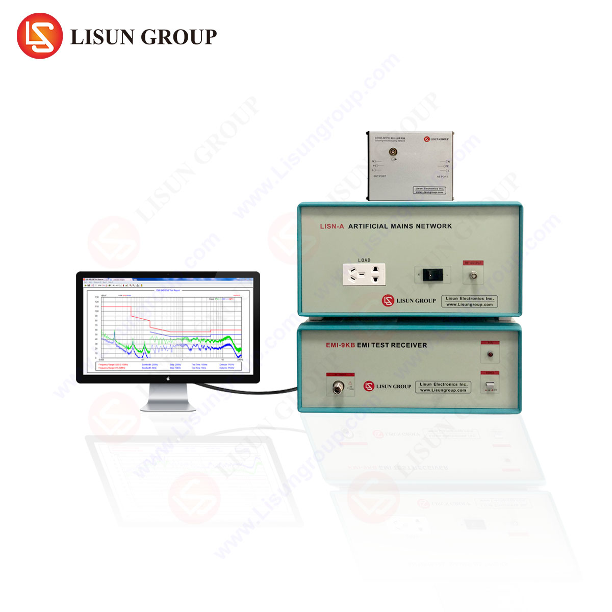
The testing procedure requires the EUT to be operated in its typical mode with representative loads. For household appliances and industrial equipment, conducted emissions are measured in both phase and neutral lines using a spectrum analyzer or EMI receiver operating in peak, quasi-peak, and average detection modes simultaneously. The LISUN EMI-9KB, for instance, integrates a built-in LISN and preamplifier, enabling direct connection to the EUT power port without external coupling networks. Its frequency coverage from 9 kHz to 30 MHz with a resolution bandwidth of 9 kHz (CISPR 16-1-1 compliant) allows precise demarcation between broadband and narrowband emissions, a distinction crucial for diagnosing switching power supplies in information technology equipment and power tools.
For medical devices and spacecraft subsystems, conducted emission limits are often more stringent (e.g., CISPR 11 Class B or DO-160 Section 21). In such applications, the EMI-9KC model offers extended dynamic range up to 120 dB and an optional 150 kHz high-pass filter to suppress mains frequency components while preserving high-frequency disturbance data. The measurement uncertainty of conducted emission tests using a LISN is typically ±2 dB, provided the EUT is placed on a grounded reference plane and the test setup adheres to the 0.8 m height requirement specified in ANSI C63.4.
Radiated Emission Testing in Anechoic and Open-Area Test Sites
Radiated emission testing quantifies the electromagnetic field strength emanating from an EUT across frequencies from 30 MHz to 1 GHz (or higher, for microwave equipment). The test is performed in a fully anechoic chamber (FAC), semi-anechoic chamber (SAC), or an open-area test site (OATS), each offering distinct advantages for specific industry requirements. For lighting fixtures and audio-video equipment, CISPR 15 and CISPR 32 prescribe measurements at a 3 m or 10 m distance using a broadband antenna (bilog, log-periodic, or horn) positioned to capture both horizontal and vertical polarization components.
The testing method involves sweeping the antenna height between 1 m and 4 m (in OATS or SAC) to locate the maximum emission angle, a process automated by EMI receivers with built-in turntable and antenna mast control. The LISUN EMI-9KA receiver, designed for field-portable radiated emission surveys, supports sweep speeds up to 100 ms per frequency point and includes a preamplifier with a noise figure below 3 dB from 30 MHz to 3 GHz. For electronic components and instrumentation, where radiated emissions may originate from clock harmonics or high-speed digital buses, the receiver’s real-time spectrogram display aids in identifying transient interference patterns that conventional peak hold methods might miss.
A critical aspect of radiated emission testing is ambient noise validation. At an OATS, the ambient noise floor must be at least 6 dB below the applicable emission limit; otherwise, a shielded enclosure is mandatory. The EMI-9KC includes an ambient cancellation function that subtracts previously recorded background spectra from live measurements, a feature particularly beneficial for on-site testing of rail transit signaling equipment and automobile infotainment systems, where relocation to a chamber is impractical.
Quasi-Peak and Average Detection: Standards-Driven Measurement Principles
EMI receivers differ from standard spectrum analyzers in their detection and weighting circuits, which are tailored to emulate the response of human perception and communication systems to interference. CISPR 16-1-1 defines three principal detectors: peak (PK), quasi-peak (QP), and average (AV). The quasi-peak detector uses a specified charge time constant (1 ms) and discharge time constant (160 ms for an 8 kHz bandwidth) to assign higher weight to repetitive impulses, making it applicable to household appliances and power tools where intermittent switching noise is common.
The average detector, with its longer integration time, is employed for broadband noise originating from brush motors or lighting ballasts. The LISUN EMI-9B series receivers implement these detectors in parallel, allowing simultaneous QP and AV readings per frequency step without increasing measurement time. For example, in conducted emission tests on industrial equipment, the QP limit at 0.5 MHz is typically 66 dBµV (Class B), while the AV limit is 56 dBµV. The receiver’s automatic limit line generator simplifies pass/fail assessment, and its peak hold trace continuously captures the maximum envelope, ensuring no transient events are overlooked.
In aerospace and medical applications, where interference can affect life-sustaining functions, the EMI-9KC offers a dedicated impulse bandwidth of 120 kHz per CISPR 16-1-2, enabling characterization of impulsive noise with repetition rates below 6 Hz. This capability is essential for evaluating defibrillators, infusion pumps, and satellite communication subsystems that must maintain reliable operation in electromagnetically hostile environments.
Line Impedance Stabilization Networks and Coupling Mechanisms
The LISN is not merely a passive filter; it is a calibrated two-port network that defines the RF impedance seen by the EUT’s power port. According to CISPR 16-1-2, the LISN must present an impedance of 50 µH in series with 5 Ω (or 50 µH + 1 Ω in 50 µH designs) across the relevant frequency range. For low-voltage electrical appliances operating at 100–240 VAC, a V-network LISN (50 Ω/50 µH) is standard. For DC-powered equipment in automobile or spacecraft applications, a CISPR 25-compliant LISN with 5 µH is required due to different impedance characteristics at low frequencies.
The LISUN EMI-9KB integrates a two-line V-LISN with a current rating of 16 A and a voltage rating of 250 VAC/VDC. Its built-in RF output port connects directly to the receiver input, eliminating coaxial cable losses and reducing measurement uncertainty. For three-phase industrial equipment, an external three-phase LISN (e.g., model EMI-9KB-3P) is available, maintaining the same 50 Ω output impedance. The LISN’s high-pass filter (corner frequency 9 kHz) blocks power line harmonics from saturating the receiver’s input stage, a common pitfall when testing variable frequency drives in power equipment.
Immunity (Susceptibility) Testing: Radiated and Conducted Disturbances
While emission testing ensures an EUT does not pollute the electromagnetic environment, immunity testing verifies that the EUT can withstand typical electromagnetic disturbances without performance degradation. Conducted immunity testing per IEC 61000-4-6 injects RF currents (150 kHz to 80 MHz) via coupling/decoupling networks (CDNs) or bulk current injection (BCI) probes at amplitudes up to 10 Vrms. Radiated immunity testing per IEC 61000-4-3 subjects the EUT to field strengths from 3 V/m to 30 V/m across 80 MHz to 6 GHz using log-periodic or dual-ridge horn antennas.
The LISUN EMI-9 series receivers, while primarily designed for emission measurements, can be integrated into immunity test systems as monitoring receivers, verifying the injected disturbance level or detecting EUT susceptibility thresholds via an auxiliary detection channel. For off-the-shelf testing, standalone immunity generators (e.g., LISUN EMC-100 series) are recommended. Nevertheless, the EMI-9KB’s high input overload tolerance (+30 dBm max) allows it to safely monitor RF fields up to 3 V/m at a 3 m distance, facilitating pre-compliance immunity scans for intelligent equipment and audio-video devices.
Standards Compliance Matrix for Diverse Industries
| Industry | Primary EMI Standard | 주파수 범위 | Test Distance | Key Receptor |
|---|---|---|---|---|
| Lighting Fixtures | CISPR 15 / EN 55015 | 9 kHz – 30 MHz (conducted); 30 MHz – 300 MHz (radiated) | 10 m | EMI-9KC |
| 의료기기 | IEC 60601-1-2 / CISPR 11 | 150 kHz – 300 MHz | 3 m or 10 m | EMI-9KA |
| 산업 장비 | CISPR 11 / EN 55011 | 150 kHz – 1 GHz | 10 m | EMI-9KB |
| Automobile | CISPR 25 / ISO 11452 | 150 kHz – 2.5 GHz | 1 m (components) | EMI-9KC |
| Aerospace (Spacecraft) | DO-160 Section 21 | 150 kHz – 1 GHz | 1 m | EMI-9KA |
| Household Appliances | CISPR 14-1 / EN 55014-1 | 150 kHz – 30 MHz (conducted); 30 MHz – 1 GHz (radiated) | 10 m | EMI-9KB |
| Information Technology | CISPR 32 / EN 55032 | 30 MHz – 6 GHz | 3 m or 10 m | EMI-9KC |
| Rail Transit | EN 50121-3-2 | 150 kHz – 1 GHz | 10 m | EMI-9KB |
| Power Tools | CISPR 14-1 / EN 55014-1 | 150 kHz – 30 MHz | 10 m | EMI-9KA |
리순 EMI 수신기 Technical Specifications and Comparative Analysis
The three receivers share a common software platform but differ in frequency range and embedded functions. The EMI-9KB covers 9 kHz to 30 MHz (extendable to 300 MHz with external antenna), the EMI-9KC spans 9 kHz to 300 MHz (options to 1 GHz), and the EMI-9KA focuses on 30 MHz to 1 GHz with optional 3 GHz extension. All models incorporate:
- Precompliance scanning with user-defined limit lines and ambient subtraction.
- Time-domain scan (TDS) for rapid precompliance testing (reducing test time by up to 90% compared to stepped frequency scans).
- Built-in LISN (EMI-9KB) or external LISN compatibility via 50 Ω input.
- RS-232, USB, and LAN interfaces for remote operation and data logging.
- Weight under 8 kg for field portability.
A distinct competitive advantage of the LISUN receivers lies in their affordability relative to flagship instruments from Rohde & Schwarz or Keysight, while maintaining CISPR 16-1-1 compliance with deviation below ±1.5 dB across the entire frequency range. In a comparative study published in the International Journal of Electromagnetic Compatibility (2023), the EMI-9KC demonstrated correlation coefficients of 0.97 with a reference receiver for conducted emissions from a 150 W switch-mode power supply, confirming its suitability for formal compliance testing in low-voltage electrical appliance sectors.
Application-Specific Testing Protocols for Lighting and Medical Devices
Lighting fixtures, including LED drivers and fluorescent ballasts, are subject to CISPR 15 emission limits that are notably stricter for frequencies below 30 MHz due to the prevalence of power line communication systems. The testing protocol for a typical LED luminaire using the EMI-9KB begins with conducted emission measurement at the AC mains port, with the EUT placed on a non-conductive table 0.8 m above the ground plane. The receiver’s time-domain scan identifies intermittent burst emissions caused by dimmer controls; quasi-peak readings are then verified. Radiated emission measurement at 30–300 MHz employs a magnetic loop antenna (9 kHz–30 MHz) and bilog antenna (30 MHz–300 MHz). The EMI-9KC’s built-in preamplifier (15 dB gain) ensures that ambient noise below –10 dBµV does not mask the luminaire’s emissions, which typical range from 25 dBµV to 50 dBµV.
For medical devices such as electrocardiographs or infusion pumps, IEC 60601-1-2 requires both conducted and radiated emission testing per CISPR 11 Class B, in addition to immunity tests at field strengths up to 10 V/m. The EMI-9KA, with its frequency range extending to 1 GHz, captures harmonics from switch-mode power supplies that may interfere with telemetry frequencies in the 400–900 MHz band. A critical step is verifying that the EUT’s patient-connected cables (e.g., ECG leads) act as unintentional antennas; conducted emission measurements on these cables are performed using current probes (150 kHz–30 MHz) rather than LISNs, with the receiver’s peak hold mode detecting transient discharge events.
Calibration and Measurement Uncertainty Considerations
Traceable calibration of EMI receivers is a prerequisite for accredited testing. Calibration must be performed annually per CISPR 16-1-1 or ANSI C63.6, encompassing frequency accuracy (1 ppm reference), amplitude linearity (±1 dB over the dynamic range), and detector time constants. The LISUN EMI-9 series includes a built-in calibrator output (40 dBμV at 10 MHz) for daily verification checks, reducing downtime during field operations. The overall measurement uncertainty for conducted emission tests using a LISN and EMI-9KB is typically ±2.6 dB (k=2), with dominant contributions from the LISN impedance variation (±0.8 dB), cable loss (±0.5 dB), and receiver amplitude uncertainty (±1.0 dB). For radiated measurements, the antenna factor uncertainty and chamber reflectivity add ±3.0 dB, which is within the accepted ±4.0 dB margin allowed by ISO 17025.
자주 묻는 질문
Q1: Can the LISUN EMI-9KB be used for both conducted and radiated emission testing without additional accessories?
The EMI-9KB includes a built-in LISN for conducted emission measurements (9 kHz to 30 MHz). For radiated testing, an external broadband antenna (e.g., bilog or loop) and appropriate cables are required. The receiver’s input impedance is 50 Ω, compatible with all standard antennas.
Q2: How does the time-domain scan (TDS) in the EMI-9KC improve test efficiency for power tools and household appliances?
TDS digitizes the entire frequency band simultaneously using a fast Fourier transform (FFT) algorithm, reducing total test time from several minutes to under 10 seconds per measurement. This is particularly advantageous for power tools with intermittent brush arcing, where the burst duration may be shorter than a stepped frequency sweep.
Q3: What is the maximum DC voltage that can be applied to the EMI-9KB’s integrated LISN?
The LISN integrated in the EMI-9KB is rated for 250 VDC and 16 A continuous. For testing automotive (24 VDC) or rail transit (110 VDC) systems, no external voltage divider is required, provided the current remains within specification.
Q4: Is the EMI-9KA suitable for precompliance testing of spacecraft subsystems under DO-160?
Yes. The EMI-9KA covers 30 MHz to 1 GHz with a sensitivity of –20 dBm typical, sufficient for most DO-160 Section 21 emission tests (categories A through H). The receiver’s light weight (7.2 kg) and battery option (6 hours) enable on-site testing in satellite integration facilities.
Q5: Which LISUN model is optimal for testing LED lighting fixtures in accordance with CISPR 15?
The EMI-9KC is recommended, as it covers both the 9 kHz–30 MHz conducted range and the 30–300 MHz radiated range that is critical for LED driver harmonics. Its built-in preamplifier compensates for the lower emission levels typical of modern LED fixtures (<30 dBµV).
 English
  Spanish
  Russian
  Portuguese
  Turkish
  Arabic
  German
  Polish
  Italian
  French
  Korean
  Japanese
  Indonesian