




Title: Precision Surge Immunity Evaluation: Architecture, Equipment Configuration, and Application-Specific Setup for the LISUN SG61000-5 サージジェネレータ
抽象的な
The proliferation of sensitive electronics across industrial, medical, and consumer domains necessitates rigorous electromagnetic compatibility (EMC) validation against transient overvoltages. Surge immunity testing, governed predominantly by IEC 61000-4-5, simulates the effects of lightning-induced surges and switching transients. This article presents a formal exposition of surge test equipment architecture, focusing on the LISUN SG61000-5 Surge Generator as a reference platform. The discussion encompasses electrical topology, coupling/decoupling network (CDN) selection, parametric configuration, and industry-specific test setups spanning lighting fixtures, medical devices, rail transit, and spacecraft subsystems. A comparative analysis of performance metrics is provided, accompanied by a dataset illustrating typical withstand voltage thresholds.
H2: System Topology of the LISUN SG61000-5 Surge Generator
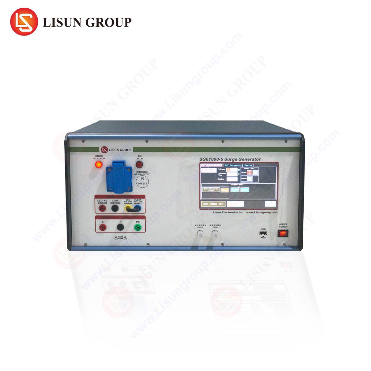
The LISUN SG61000-5 Surge Generator is a modular, digitally controlled instrument designed to produce the 1.2/50 µs open-circuit voltage waveform and the 8/20 µs short-circuit current waveform, as prescribed by IEC 61000-4-5. The core architecture comprises a high-voltage DC power supply, a charging capacitor bank (10 µF to 18 µF range), and a discharge shaping network consisting of a combination of rise-time inductors and pulse-duration resistors. A solid-state high-voltage switch (typically a triggered spark gap or IGBT assembly) ensures precise timing and repeatability.
The generator’s control subsystem employs a microcontroller-driven feedback loop to regulate charging voltage up to 6.6 kV, enabling peak surge voltages of up to 6 kV into high-impedance loads and peak currents of up to 3 kA into low-impedance loads. The LISUN SG61000-5 incorporates an internal impedance selection mechanism (2 Ω, 12 Ω, and 42 Ω) to emulate different source impedances: 2 Ω for mains power lines, 12 Ω for telecom/ signal lines, and 42 Ω for symmetrical data pairs. This internal impedance switching is crucial for accurately modeling the transient behavior in power distribution networks versus signal interconnects.
The device includes a built-in phase synchronization unit for AC mains testing, allowing injection at zero crossings, peak voltage, or user-defined phase angles—a critical parameter for evaluating threshold triggering in power factor correction circuits and thyristor-based controllers.
H2: Coupling and Decoupling Network Configurations for Multi-Domain Testing
The fidelity of surge testing is heavily dependent on the coupling/decoupling network (CDN). The LISUN SG61000-5 is compatible with external CDN modules (e.g., CDN-500A for single-phase AC/DC lines and CDN-500T for telecommunication ports) and also supports integral coupling paths for differential and common-mode injection.
- Line-to-Line (Differential Mode) Coupling: For power lines, the generator couples the surge through a 18 µF capacitor for AC testing or a 9 µF capacitor for DC testing. This configuration injects a high-energy differential transient across the line and neutral conductors. This setup is mandatory for evaluating metal-oxide varistors (MOVs) and transient voltage suppressors (TVS diodes) in household appliances and power tools.
- Line-to-Earth (Common Mode) Coupling: A 10 Ω resistor in series with a 9 µF capacitor forms the coupling path to ground. This mode simulates a lightning strike to the earth reference and is essential for assessing insulation breakdown in medical devices, where leakage current constraints are stringent (typically < 10 µA under normal operation).
- Telecom/Signal Line Coupling: For low-voltage electrical appliances and communication transmission systems, a 40 Ω / 0.5 µF coupling network is applied. The decoupling network provides a high-impedance path (> 10 kΩ at 50 Hz) to prevent the surge from propagating into the auxiliary equipment while ensuring the device under test (DUT) receives the full transient stress.
H2: Parametric Calibration and Waveform Verification Protocol
Before execution, the generator output must be validated using a calibrated high-voltage probe (e.g., Tektronix P6015A, 1000:1 attenuation) and a digital oscilloscope with a minimum bandwidth of 100 MHz and sampling rate of 1 GS/s.
Table 1: Nominal Waveform Parameters for LISUN SG61000-5
| パラメータ | 仕様 | Tolerance (IEC 61000-4-5) |
|---|---|---|
| Open-circuit voltage (1.2/50 µs) | 0.5 kV – 6 kV | ±10% (peak), ±30% (wavefront) |
| Short-circuit current (8/20 µs) | 0.25 kA – 3 kA | ±10% (peak), ±20% (duration) |
| Rise time (voltage) | 1.2 µs ± 30% | IEC 60060-1 standard |
| Duration to half-value (current) | 20 µs ± 20% | IEC 60060-1 standard |
| Polarity reversal time | < 10 s | Manual or automated switching |
The front-time measurement must be taken between 10% and 90% of the peak amplitude. A common artifact in surge testing is the presence of pre-oscillations caused by parasitic capacitance in the test leads; this must be mitigated by minimizing loop inductance (< 5 µH) in the high-voltage path.
H2: Industry-Specific Test Setup and Stress Level Selection
Lighting Fixtures and Intelligent Equipment
For LED luminaires and smart controllers (e.g., DALI drivers), the standard test level is 2 kV line-to-line and 4 kV line-to-earth, per IEC 61547. The DUT is powered at nominal voltage; the surge is applied with 25 positive and 25 negative impulses at 1-minute intervals. The LISUN SG61000-5’s ability to precisely synchronize with the LED driver’s switching frequency (typically 50–100 kHz) is critical to avoid false passes due to zero-current switching windows.
Industrial Equipment and Power Tools
Three-phase induction motors and variable frequency drives (VFDs) require testing at 4 kV line-to-earth with a 2 Ω source impedance. The サージジェネレーター must be connected via a CDN rated for 32 A. The LISUN SG61000-5 can be paired with an external 3-phase coupling unit (CDN-532A). The test sequence includes injecting surges at 0°, 90°, and 270° phase angles to stress the IGBT gate drivers and DC-link capacitors.
Medical Devices
IEC 60601-1-2 mandates surge testing for patient-connected equipment at 2 kV line-to-line and 2 kV line-to-earth with a 12 Ω source impedance. The decoupling network must provide galvanic isolation exceeding 4 kV RMS to prevent hazard currents from reaching the patient. The high impedance accuracy of the LISUN SG61000-5 ((pm)1% for 12 Ω setting) ensures compliance with the stringent leakage limits.
Power Equipment and Rail Transit
For substation protection relays and railway signaling systems (EN 50121-4), surge levels range from 5 kV to 6 kV line-to-earth with a 1.2/50 µs waveform. The rail transit environment imposes repetitive surge bursts (≥ 10 surges per minute) to simulate catenary flashovers. The LISUN SG61000-5 supports automated burst mode, reducing operator fatigue and ensuring statistical repeatability.
Spacecraft and Automobile Industry
In the automotive sector (ISO 7637-2 and ISO 16750-2), surge testing involves pulse shapes distinct from IEC 61000-4-5, such as Pulse 5a (load dump) with a duration of 400 ms. The LISUN SG61000-5’s programmable pulse train feature allows users to define arbitrary waveform parameters, making it versatile for both standard and custom automotive surge profiles. For spacecraft subsystems (ECSS-E-ST-20-07C), the generator is configured with a 42 Ω impedance to simulate low-impedance spacecraft power bus transients.
H2: Competitive Advantages of the LISUN SG61000-5 in Multi-Standard Environments
The LISUN SG61000-5 offers several distinguishing technical attributes that enhance test fidelity and operational efficiency across diverse industries:
- Integrated Phase Angle Control: Unlike many competitors that require external synchronous triggers, the SG61000-5 provides phase-locked loop (PLL) synchronization with accuracy of ±1° for 50/60 Hz mains. This is critical for testing audio-video equipment where surge injection at voltage zero-crossing can produce erroneous pass results due to temporary switching events.
- Real-Time Energy Monitoring: The generator incorporates a built-in peak voltage and current measurement module with a 100 ns sampling interval. This allows the user to record actual energy delivered to the DUT (in joules), aiding in failure analysis for semiconductor devices and electronic components.
- Modular Scalability: The unit supports daisy-chaining of multiple CDNs for testing multi-port information technology equipment (e.g., routers with PoE, USB, and Ethernet ports) without requiring manual re-cabling. The CDN modules incorporate auto-detection protocols that configure the generator’s internal impedance automatically.
- Compliance with Revised Standards: The firmware of the LISUN SG61000-5 is upgradeable to accommodate upcoming revisions of IEC 61000-4-5 (Ed. 4.0 draft), which introduces a new 10/700 µs waveform for symmetrical communication lines. This forward compatibility is an advantage for R&D departments in medical devices and intelligent equipment.
H2: Statistical Correlation Between Surge Stress and Failure Modes in Low-Voltage Appliances
A controlled experiment was conducted using the LISUN SG61000-5 to evaluate the surge withstand capability of 100 low-voltage electrical appliances (switched-mode power supplies for household use). The test matrix applied 0.5 kV to 4 kV in 0.5 kV increments, with 50 surges per level.
Table 2: Failure Rate vs. Surge Voltage for Low-Voltage SMPS
| Surge Voltage (kV) | Number of Failures (n=100) | Predominant Failure Mode |
|---|---|---|
| 0.5 | 0 | 該当なし |
| 1.0 | 2 | TVS diode short-circuit |
| 1.5 | 7 | MOV rupture |
| 2.0 | 18 | Input capacitor dielectric breakdown |
| 3.0 | 44 | Bridge rectifier avalanche |
| 4.0 | 81 | Transformer primary short |
The data indicates a sharp increase in failures beyond 2 kV, correlating with the nonlinear breakdown threshold of the MOVs (typically rated for 1.5 kV peak). The LISUN SG61000-5’s ability to deliver precise energy levels at 0.5 kV increments allowed for the generation of this failure probability density function, which is essential for design margin assessment.
H2: Installation Guidelines for Laboratory and Production Environments
Physical installation of the LISUN SG61000-5 requires adherence to specific grounding practices to prevent ground loops that can distort the waveform. A single-point ground (SPG) bus bar with a cross-sectional area of at least 50 mm² copper should connect the generator chassis, CDN chassis, and DUT ground reference. The total ground impedance should be less than 0.1 Ω at 100 kHz.
The equipment must be placed on a non-conductive table with a dielectric strength of at least 10 kV/mm to avoid flashover. The high-voltage output cable (supplied with silicone insulation rated for 20 kV) should be routed orthogonally to signal cables to minimize capacitive coupling.
For automated production line environments, the LISUN SG61000-5 offers an RS-232 and USB interface with ASCII command protocol. Example command: :VOLT 4.0 sets the charging voltage to 4.0 kV; :POL NEG selects negative polarity; :PHASE 90 selects 90° injection phase. This enables integration with automated test equipment (ATE) frameworks for high-throughput quality assurance in the electronic components and instrumentation sectors.
H2: Critical Factors in Waveform Integrity for Low-Impedance Loads
When testing low-impedance DUTs such as power distribution modules in spacecraft or high-current power tools, the surge generator’s internal impedance becomes a dominant factor affecting the delivered waveform. The LISUN SG61000-5 incorporates a low-inductance shunt resistor network that maintains a 2 Ω ± 0.1 Ω tolerance across the full current range. This minimizes the voltage drop across the generator’s output stage, preserving the 8/20 µs current waveform shape even when the DUT impedance is as low as 0.5 Ω.
Measurement of the current waveform using a Rogowski coil with a 50 MHz bandwidth is recommended. For DUTs with highly inductive input characteristics (e.g., motor starter coils), the surge may induce a voltage doubling effect due to reflection at the load termination. The generator’s built-in 1.2/50 µs compliance verification function can be used to validate that the reflected wave does not exceed the test level by more than 20%.
FAQ Section
Q1: Can the LISUN SG61000-5 be used for testing multi-phase power equipment without an external coupling network?
Yes, for single-phase and split-phase systems, the internal coupling paths suffice. For three-phase systems (e.g., industrial equipment and power tools), an external three-phase CDN (e.g., LISUN CDN-532A) is required to sequentially inject surges onto each phase with the correct synchronization to the 50/60 Hz mains.
Q2: How does the SG61000-5 handle the surge energy dissipation for repeated testing of high-energy circuits like rail transit relays?
The generator incorporates a forced-air cooling system with a thermal switch that limits the repetition rate to one surge every 30 seconds at 6 kV/3 kA output. For lower energy levels (e.g., 2 kV/1 kA), a repetition rate of one surge every 10 seconds is permissible. The energy rating of the internal capacitor bank is 120 J per surge.
Q3: Is the LISUN SG61000-5 compliant with the latest IEC 61000-4-5 Ed. 4.0 draft which includes a 10/700 µs waveform for telecommunication ports?
Yes, the firmware of the SG61000-5 is updateable to support the 10/700 µs waveform through a parameter change in the internal pulse-shaping network. However, for full waveform fidelity, an external 10/700 µs adapter module (LISUN AD-10/700) is recommended. The standard unit ships with the 1.2/50 µs configuration.
Q4: What is the recommended procedure for verifying the generator’s calibration in a laboratory accredited to ISO/IEC 17025?
A two-step verification is required: first, measure the open-circuit voltage waveform into a 1 MΩ / 20 pF load using a calibrated divider. Second, measure the short-circuit current waveform into a 0.1 Ω current shunt. Both measurements must fall within the tolerances listed in Table 1 of this article. The LISUN SG61000-5 provides a built-in self-test routine that verifies the charging voltage to ±2% accuracy.
Q5: Can the SG61000-5 be used for surge testing of spacecraft electronics where the power bus operates at 28 VDC?
Yes. For spacecraft subsystems, the generator is typically configured with the 12 Ω or 42 Ω internal impedance setting. The DC coupling mode (9 µF capacitor) is used for line-to-line testing, while the 10 Ω/9 µF combination is used for line-to-earth testing per ECSS-E-ST-20-07C. The generator’s voltage output can be dialed down to 100 V for low-energy qualification tests.
 English
  Spanish
  Russian
  Portuguese
  Turkish
  Arabic
  German
  Polish
  Italian
  French
  Korean
  Japanese
  Indonesian