

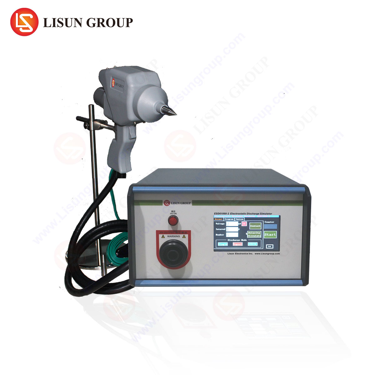



A Comprehensive Guide to Electrostatic Discharge Gun Testing for Product Qualification
Fundamental Principles of Electrostatic Discharge Phenomena
Electrostatic discharge (ESD) represents a transient transfer of electric charge between two objects at different electrostatic potentials, occurring through direct contact or via an ionized ambient dielectric. This phenomenon, a subset of Electrical Fast Transient (EFT) events, poses a significant threat to the operational integrity and long-term reliability of electronic systems across all industrial sectors. The underlying mechanism involves the accumulation of static electricity on a human body or a charged object, frequently generated through triboelectric effects such as friction, followed by rapid discharge upon contact with an electronic device. The resulting current pulse, which can rise to several amperes within a nanosecond, injects high-frequency energy into the circuit. This energy can induce catastrophic failures, such as dielectric breakdown in semiconductor junctions, or latent defects that degrade performance and lead to premature field failures. Understanding this fundamental behavior is critical for developing effective testing methodologies that accurately simulate real-world ESD events to ensure product robustness.
International Standardization Framework for ESD Immunity Testing
The global framework for ESD immunity testing is primarily defined by the International Electrotechnical Commission (IEC) 61000-4-2 standard. This standard meticulously outlines the test methodology, including the waveform parameters of the discharge current, the test environment specifications, the test setup geometry, and the procedure for applying discharges. The standard defines two distinct discharge methods: contact discharge and air discharge. Contact discharge testing involves physically contacting the ESD gun to the Equipment Under Test (EUT) before activating the discharge, providing a highly repeatable method for testing conductive surfaces. Air discharge simulates a spark jumping through the air from the gun to the EUT, which is applicable for testing surfaces coated with non-conductive materials like paint or plastic. The IEC 61000-4-2 standard specifies a current waveform with a very fast rise time of 0.7 to 1 nanosecond to the initial peak current, followed by a decay to 50% of the peak value at 30 nanoseconds and further to lower percentages at 60 nanoseconds. Compliance with this precise waveform is non-negotiable for generating valid and reproducible test results that are recognized by certification bodies worldwide.
Architecture and Operational Mechanics of an ESD Simulator
An Simulatore ESD, or ESD gun, is a sophisticated instrument engineered to generate highly repeatable and standardized ESD pulses. Its architecture comprises several critical subsystems. A high-voltage DC power supply is responsible for charging a storage capacitor to a pre-defined test voltage, which can typically range from a few hundred volts up to 30 kV. This capacitor, in conjunction with a discharge resistor, forms the core of the pulse-shaping network. The values of these components are meticulously selected to generate the current waveform specified in standards like IEC 61000-4-2. A relay switch mechanism controls the discharge event, ensuring a precise and consistent release of the stored energy. The discharge current is then delivered to the EUT through a interchangeable discharge tip. For the instrument to maintain calibration and testing integrity, it must be verified periodically using a target, which is a specialized current transducer connected to an oscilloscope with sufficient bandwidth (typically >2 GHz). The measured waveform is compared against the standard’s tolerance limits for parameters like peak current, rise time, and current levels at 30 ns and 60 ns.
Introduzione al LISUN ESD61000-2 ESD Simulator
The LISUN ESD61000-2 represents a state-of-the-art electrostatic discharge simulator designed for full compliance with the most stringent international standards, including IEC 61000-4-2, ISO 10605, and ANSI C63.16. It serves as a critical tool for design verification and quality assurance laboratories seeking to validate the ESD immunity of their products. The instrument is engineered for superior performance, featuring a wide test voltage range from 0.1 kV to 30 kV, accommodating both the standard compliance levels for air and contact discharge (typically up to 8 kV for contact and 15 kV for air) and higher stress levels required by specific industries such as automotive.
Key Specifications of the LISUN ESD61000-2:
- Test Voltage: 0.1 ~ 30 kV (adjustable with 0.1 kV resolution for contact discharge, 0.1 ~ 16.5kV and 16.5 ~ 30kV for air discharge).
- Test Modes: Contact discharge and Air discharge.
- Polarità: Positive and Negative.
- Discharge Interval: 0.1 ~ 999 seconds programmable.
- Discharge Count: 1 ~ 9999 programmable.
- Modalità operative: Single discharge, 20 discharges per second.
- Conformità agli standard: IEC 61000-4-2, GB/T 17626.2, ISO 10605.
The testing principle of the ESD61000-2 revolves around its precision high-voltage generation and switching circuitry. It utilizes a programmable power supply to charge its main energy storage capacitor (150 pF) to the exact test voltage. For contact discharge, a vacuum relay ensures a stable connection before a high-speed semiconductor switch releases the pulse through a 330-ohm discharge resistor, generating the characteristic fast-rising waveform. The user interface, often featuring a color LCD and intuitive navigation, allows test engineers to configure complex test sequences with high repeatability.
Industry-Specific Application Scenarios for ESD Testing
The application of ESD testing using instruments like the LISUN ESD61000-2 is ubiquitous across modern technology sectors.
In the Automobile Industry, electronic control units (ECUs) for engine management, braking (ABS), and infotainment are tested per ISO 10605, which often requires higher discharge levels than IEC 61000-4-2 due to the harsher electrostatic environment within a vehicle. For Dispositivi medici, such as patient monitors and infusion pumps, ESD immunity is a matter of patient safety. A discharge to a control panel must not cause a malfunction that could endanger a patient. Intelligent Equipment E Elettrodomestici with touch-sensitive controls and wireless connectivity are highly susceptible; testing ensures that a discharge does not cause a system lock-up or corrupted memory. Communication Transmission equipment, including routers and base stations, must maintain uninterrupted service, making ESD immunity critical for network reliability.
IL Apparecchi di illuminazione industry, particularly with the proliferation of LED drivers and smart lighting systems, uses ESD testing to prevent driver IC failure or flickering. In Apparecchiature industriali E Power Tools, where variable-frequency drives and digital controllers operate in noisy environments, ESD testing validates robustness against operator-induced discharges. For Electronic Components E Instrumentation, component-level ESD robustness (often tested using Human Body Model (HBM) and Charged Device Model (CDM) standards) is verified before integration, while system-level testing with an ESD gun validates the final product’s enclosure and port protection.
Methodology for Executing a Compliant ESD Test
Executing a standardized ESD test is a systematic process. The initial phase involves establishing a controlled test environment, with the EUT placed on a grounded horizontal coupling plane (HCP) and, if used, a vertical coupling plane (VCP). The ESD simulator’s ground return cable must be connected securely to the reference ground of the HCP. The test begins with a pre-test verification of the simulator’s output waveform using a current target to ensure it falls within the standard’s specified limits.
The test proper involves selecting test points on the EUT based on a risk analysis; these typically include any user-accessible metal parts, gaps between insulating parts, and display areas. For each point, the test engineer applies a series of discharges at the specified test level (e.g., ±4 kV for contact, ±8 kV for air). The discharge application follows a “single-discharge” method, where the EUT is allowed to respond between each discharge, or a more stressful “burst” mode. The EUT is monitored throughout the test for any degradation of performance or functionality, classified according to its performance criteria (e.g., normal performance within specification, temporary loss of function that self-recovers, or permanent failure). A comprehensive test report documents the test setup, configuration, levels applied, and the EUT’s performance.
Comparative Analysis of ESD Simulator Performance Metrics
When evaluating ESD simulators, key performance metrics differentiate basic models from precision instruments like the LISUN ESD61000-2. Waveform fidelity is paramount; the generated current pulse must adhere strictly to the tolerances defined in the standard. The stability and accuracy of the high-voltage power supply directly influence the repeatability of test results across thousands of discharge cycles. A critical differentiator is the switching technology; the use of a high-speed semiconductor switch in advanced models offers superior longevity and consistency compared to traditional spark-gap switches, which can suffer from erosion and parameter drift over time.
User interface and programmability are also significant. The ability to program complex test sequences—varying voltage, polarity, and discharge interval automatically—enhances testing efficiency and eliminates operator-induced errors. Furthermore, robust construction and ergonomic design reduce user fatigue during extended testing sessions and contribute to the long-term reliability of the instrument itself. The LISUN ESD61000-2’s design emphasizes these factors, providing a stable, repeatable, and user-friendly platform for critical compliance testing.
Troubleshooting Common ESD Test Implementation Challenges
Several challenges can arise during ESD testing that can compromise the validity of results. Inconsistent or failed air discharges are often due to the approach speed and angle of the ESD gun; the standard specifies a swift, perpendicular approach until discharge occurs. If discharges are not triggering, the voltage may be insufficient for the air gap, or the tip may be approaching a more recessed or better-grounded point. Excessive electromagnetic radiation from the discharge event can cause unexplained system resets; this is often a symptom of inadequate shielding or filtering on the EUT’s cables and enclosure. Ensuring all system cables are properly laid out as they would be in the field and using ferrite clamps can help mitigate this.
Another common issue is the failure to establish a consistent ground reference. A long or inductive ground strap from the ESD gun can distort the discharge waveform and lead to non-compliant testing. Ensuring a short, low-inductance connection to the coupling plane is essential. For products that repeatedly fail at specific points, the solution often involves implementing on-board protection devices such as Transient Voltage Suppression (TVS) diodes, ferrite beads, or optimizing the PCB layout to minimize loop areas that can act as antennas for the ESD energy.
Integrating ESD Immunity into the Product Development Lifecycle
To be most effective and cost-efficient, ESD immunity should not be a final gate before production but an integral consideration throughout the product development lifecycle. During the conceptual and design phases, design for ESD (DfE) principles should be applied. This includes selecting components with high inherent ESD robustness, incorporating ESD protection devices on all external interfaces (USB, Ethernet, power inputs), and implementing sound PCB design practices such as minimizing trace lengths for sensitive signals, providing unbroken ground planes, and ensuring proper clearance and creepage distances.
Prototyping is the stage where initial validation with an ESD simulator like the LISUN ESD61000-2 begins. Early and frequent testing on engineering samples allows designers to identify vulnerabilities and iterate on solutions, such as adjusting the value of a TVS diode or adding a shield. This iterative process is far less costly than discovering a fundamental design flaw during formal qualification testing or, worse, after the product has been launched to the market. Finally, in the manufacturing phase, ESD testing on pre-production and production samples serves as a critical quality control check to ensure that no process changes or component substitutions have degraded the product’s ESD immunity.
Sezione FAQ
Q1: What is the primary functional difference between contact and air discharge testing modes?
Contact discharge is applied directly to conductive surfaces of the EUT using a sharp tip, providing a highly repeatable test with a defined current path. Air discharge simulates a real-world spark and is used for insulating surfaces; its repeatability is more dependent on the operator’s approach speed and environmental factors like humidity. The LISUN ESD61000-2 is precision-engineered to ensure high repeatability in both modes.
Q2: Why is periodic verification of the ESD simulator’s output waveform mandatory?
The integrity of ESD testing is entirely dependent on the accuracy of the discharge current waveform. Components within the simulator, particularly the discharge tip and switches, can degrade over time, leading to waveform parameter drift (e.g., slower rise time, lower peak current). Regular verification against a calibrated target ensures the simulator continues to generate pulses within the strict tolerances of the standard, guaranteeing that test results are valid, comparable, and legally defensible.
Q3: For a product with a metal enclosure, where should ESD test points be focused?
The test should focus on points where a user is likely to make contact. This includes any seams or gaps in the enclosure, around buttons or switches, connector shells, and any painted or anodized areas where a discharge might arc to an underlying metal structure. The test plan should specifically target these zones to simulate the most probable real-world discharge scenarios.
Q4: Our product passed testing at ±6 kV but fails intermittently at ±8 kV. What are the likely causes?
This behavior typically indicates that the ESD protection strategy is operating at its performance limit. The protection components (e.g., TVS diodes) may have a clamping voltage that is too high, or the layout may have parasitic inductances that cause voltage overshoot. The energy from the higher-voltage discharge may be overwhelming the primary protection and causing secondary clamp circuits to activate, or it may be coupling radiatively into internal circuits. A detailed investigation of the current path and potential coupling mechanisms at the failure points is required.
 English
  Spanish
  Russian
  Portuguese
  Turkish
  Arabic
  German
  Polish
  Italian
  French
  Korean
  Japanese
  Indonesian