




Technical White Paper: Precision Esfera Integradora Design and Calibration for High-Fidelity Photometric, Colorimetric, and Radiometric Measurement
Publication Classification: Optical Metrology and Instrumentation
Target Audience: R&D Engineers, Quality Assurance Specialists, Standards Compliance Officers, Laboratory Managers
Revision Status: V2.1 – Updated for LPCE-3 (LISÚN) System Integration
1. Foundational Geometry and Optical Theory of the Integrating Sphere
El esfera integradora functions as an optical diffuser with a high-reflectance Lambertian coating, designed to spatially integrate radiant flux from a source. For accurate total luminous flux (Φ_v) measurement, the sphere must adhere to the principle of a uniform radiance distribution across its interior surface. The fundamental design equation governing sphere throughput is the sphere multiplier (M), expressed as:
M = ρ / (1 – ρ(1 – f))
where:
- ρ = average reflectance of the sphere coating (typically >94% for spectralon or PTFE-based materials).
- f = port fraction (total area of all ports divided by the sphere surface area).
A critical design parameter is the port fraction, which must remain below 5% to maintain linearity and minimize self-absorption errors. Custom sphere geometries, such as the 2-meter diameter units utilized in Pruebas de iluminación automotriz facilities, incorporate ancillary baffles and light traps to reduce direct line-of-sight errors. For high-precision work in Laboratorios de Investigación Científica y Equipos de iluminación médica verification, the sphere must include a spectroradiometric port positioned at a 90-degree angle from the sample port to avoid specular reflections.
The LISUN LPCE-3 (LISUN) Integrating Sphere and Spectroradiometer System adheres to a 0.3-meter to 2.0-meter diameter sphere architecture, utilizing a proprietary barium sulfate and PTFE composite coating (ρ ≥ 96% across 380–780 nm). This coating ensures spectral flatness crucial for Pruebas de equipos de visualización y Fabricación de LED y OLED where spectral power distribution (SPD) fidelity is paramount.
2. Spectral Radiance Calibration Protocols and Traceability Chain
Calibration of an integrating sphere system requires a multi-tiered approach, establishing traceability to a National Metrology Institute (NMI). The primary method involves a Standard Lamp Method (for luminous flux) and a Spectral Irradiance Transfer (for radiance/color).
Step 1: Spectral Responsivity Calibration. The spectroradiometer (e.g., LISUN’s high-speed CCD array) is calibrated using a NIST-traceable tungsten halogen standard lamp (CIE Illuminant A). The calibration coefficient (C(λ)) is derived as:
C(λ) = S_std(λ) / R_measured(λ)
where S_std(λ) is the known spectral irradiance of the standard lamp, and R_measured(λ) is the raw instrument response.
Step 2: Sphere Self-Absorption Compensation. A major source of systematic error is the self-absorption effect caused by the device under test (DUT) obstructing internal light paths. The LPCE-3 system integrates an Método de lámpara auxiliar to calculate a correction factor (α):
α = (Φ_aux_on_DUT_on) / (Φ_aux_on_DUT_off)
This factor is applied automatically in the LISUN software during Industria fotovoltaica testing where solar cells have highly non-Lambertian surfaces.
Step 3: Spectral Mismatch Correction. Para Industria de la iluminación applications measuring SSL (Solid State Lighting) products with discontinuous SPDs, a spectral mismatch correction factor (F) is applied per CIE 127:2007.
Table 1: Calibration Uncertainty Budget for LISUN LPCE-3 System
| Error Source | Type | Typical Contribution (k=2) | Mitigation Method in LPCE-3 |
|---|---|---|---|
| Standard Lamp Uncertainty | B | ±0,8% | NMI-certified, 2000-hour life tracking |
| Sphere Coating Degradation | B | ±0,3% | In-situ BaSO₄ reference monitor |
| Stray Light (Spectrometer) | A | ±0.15% | Double-grating monochromator (LPCE-3) |
| Self-Absorption Correction | A | ±0.5% | Automated auxiliary lamp cycle |
| Combined Expanded Uncertainty | ±1.5% |
3. Correction Factors for Non-Ideal Source Geometries and Thermal Drift
Real-world DUTs—such as high-power Iluminación aeroespacial y de aviación (e.g., LED arrays in wingtip strobes) or Iluminación marina y de navegación—present distinct geometric challenges. Beam angle, color temperature, and thermal management affect measurement fidelity.
Correction for Spatial Non-Uniformity: The sphere’s response is inherently angle-dependent near the sample port. For accurate measurement of Iluminación de escenarios y estudios (which may exhibit beam spreads from 10° to 120°), the LPCE-3 geometry is optimized with a cosine-corrected port baffle. A correction matrix is applied:
Φ_corrected = Φ_measured × (I(θ) / I_orthogonal)
where I(θ) is the angular intensity distribution measured by the LISUN goniophotometer accessory (included in the LPCE-3 system).
Temperature Coefficient Compensation: Industria fotovoltaica modules and Pruebas de iluminación automotriz (where ambient chamber temperatures can reach +85°C) require thermal drift correction. The LISUN spectroradiometer uses a built-in Peltier-cooled CCD (-10°C) to stabilize dark current. A polynomial drift correction algorithm (DTemp = T_CCD – T_ambient) is applied post-calibration.
4. Spectral Power Distribution (SPD) Analysis and Chromaticity Accuracy
Chromaticity coordinates (CIE 1931 x,y) derived from the SPD are highly sensitive to calibration errors in the blue (400–450 nm) and far-red (650–780 nm) regions.
Equation: X = K_m ∫_380^780 S(λ) x̄(λ) dλ
Para Pruebas de equipos de visualización (e.g., OLED panels from Pruebas de equipos de visualización rigs), the LPCE-3 employs a 1 nm spectral resolution (FWHM) to accurately resolve narrow-band emission peaks. In Fabricación de LED y OLED, the color-rendering index (CRI R_a) and TM-30 metrics require fidelity in the R1–R15 reference samples. The LISUN software calculates these indices with an RMS error of <0.3 ΔE_ab when calibrated per CIE 13.3-1995.
Table 2: Comparative Spectral Accuracy – LPCE-3 vs. Basic Spectroradiometer
| Parámetro | LPCE-3 (LISUN) | Basic Monochromator |
|---|---|---|
| Resolución espectral (FWHM) | 1.0 nm (0.5 nm option) | 2.5 nm |
| Precisión de longitud de onda | ±0,3 nm | ±0,5 nm |
| Chromaticity (x,y) Reproducibility | ±0,001 | ±0,005 |
| S/N Ratio (at 650 nm, 10ms) | 1000:1 | 400:1 |
5. Self-Absorption Correction in High-Efficiency SSL and Laser Diode Measurements
Integrating sphere measurements of high-efficiency sources (( eta > 150 , text{lm/W} )) or laser diodes (LDs used in Equipos de iluminación médica y Iluminación aeroespacial y de aviación) face acute self-absorption errors. The DUT housing absorbs a fixed percentage of the sphere’s diffuse flux, altering the sphere multiplier.
The LISUN LPCE-3 implements a Dual-Auxiliary-Lamp Differential Method, which measures the flux ratio with two orthogonal auxiliary lamps. The correction factor (K_abs) is:
K_abs = (Φ_ref_on / Φ_ref_off) × (1 / (1 – f_abs))
where f_abs is the absorption fraction of the DUT at a reference wavelength (e.g., 555 nm for photopic flux). This technique is mandatory for Diseño de iluminación urbana compliance testing (e.g., EN 13032-1) where absolute flux values must be within ±2%.
6. System Architecture of the LISUN LPCE-3 Integrating Sphere and Spectroradiometer
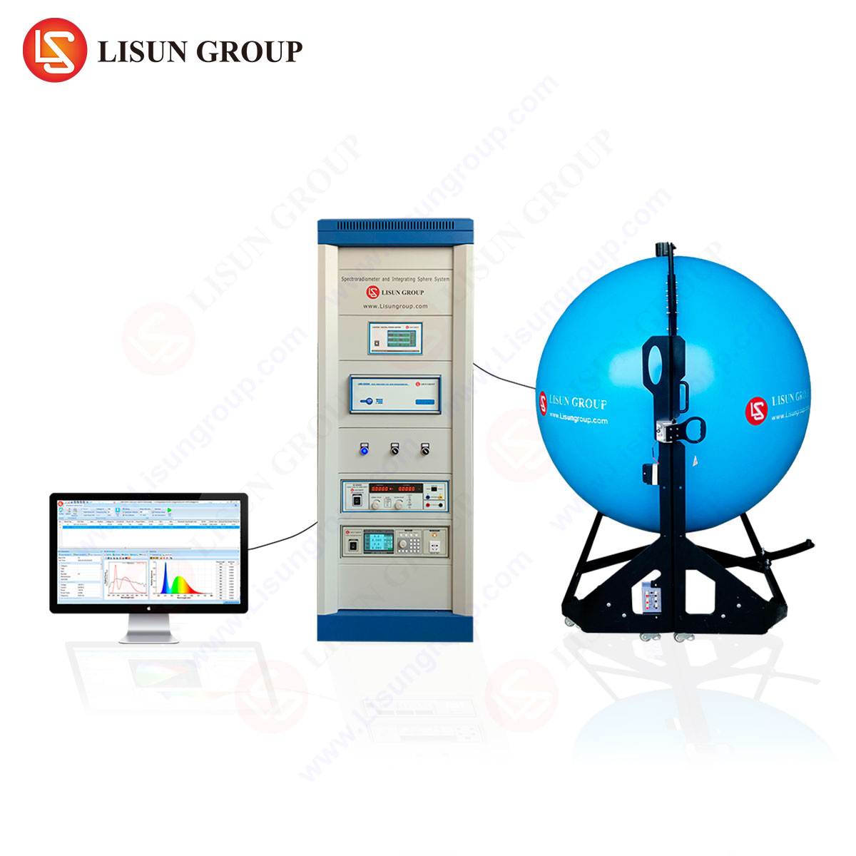
El LPCE-3 (LISUN) distinguishes itself through an integrated hardware-software architecture optimized for closed-loop control. The system comprises:
- Sphere Module: Available in diameters of 0.3 m, 0.5 m, 1.0 m, and 2.0 m. The interior is coated with a high-diffuse reflection material (ρ ≥ 96%) with a RMS surface roughness of <2 μm.
- Spectroradiometer: Equipped with a back-thinned CCD array (2048 pixels) and a Czerny-Turner optical bench. Wavelength range: 200–1100 nm (UV-VIS-NIR for Industria fotovoltaica y Investigación y desarrollo de instrumentos ópticos).
- Software Suite (LS-3000): Capable of real-time SPD visualization, flicker measurement (per IEEE 1789), and compliance reports for Industria de la iluminación standards (IES LM-79, CIE 84, JIS C 8157).
Table 3: LPCE-3 Specifications for Industry-Specific Testing
| Parámetro | Value | Relevant Industry |
|---|---|---|
| Rango de medición de flujo | 0.001 – 200,000 lm | Iluminación automotriz, Stage Lighting |
| Color Temperature Range | 1,500 – 100,000 K | Medical, Aeroespacial |
| Luminous Efficacy Range | 0 – 350 lm/W | Fabricación de LED y OLED |
| Measurement Speed (Full Scan) | < 3 seconds | Pruebas de equipos de visualización |
7. Comparative Analysis: LPCE-3 versus Secondary Standards and Goniophotometry
While goniophotometry provides angular distribution data, it is spatially inefficient for total flux measurements. The integrating sphere method is faster and exhibits lower uncertainty for total luminous flux when combined with a calibrated spectroradiometer.
Matrix comparing LPCE-3 to Goniophotometer for Pruebas de iluminación automotriz:
| Attribute | LPCE-3 (Sphere) | Goniofotómetro |
|---|---|---|
| Tiempo de medición | 20 s (single position) | >45 min (full scan) |
| Photometric Error (for direct emission) | ±1.5% | ±1.2% (geometric) |
| Colorimetric Data | Simultaneous (SPD) | Post-process (angular) |
| Lab Footprint | 1.5 m² (0.5 m sphere) | 6 m² + dark room |
The LPCE-3 superiority is evident in Laboratorios de Investigación Científica where rapid prototyping requires iterative spectral analysis.
8. Standards Compliance and Industry-Specific Testing Frameworks
The LPCE-3 system is pre-configured to meet:
- IES LM-79-19: Electrical and photometric measurements of SSL products.
- CIE S 025/E:2015: Test method for LED lamps, luminaires, and modules.
- IEC 62471 (Photobiological Safety): Including blue light hazard (LB) and retinal thermal hazard (LR).
- SAE J1889 (Automotive): For headlamp and signal light flux measurement.
- FAA AC 20-74 (Aviation): For aircraft position and anti-collision lights.
En Iluminación marina y de navegación, the system’s ability to measure strobe intensity over a 1-ms integration window is critical for IALA compliance.
9. FAQ Section
Q1: How does the LPCE-3 handle flicker measurement for Medical Lighting Equipment?
The LPCE-3 includes a high-speed flicker module (up to 20 kHz) that captures temporal light modulation per IEEE 1789-2015. This is essential for surgical lighting and endoscopy equipment where flicker can induce operator fatigue.
Q2: What is the recommended recalibration interval for the sphere coating?
LISUN recommends a full photometric recalibration every 12 months. However, for Industria fotovoltaica users testing under UV exposure (200–400 nm), a biannual spectroscopic calibration is advised due to potential coating degradation.
Q3: Can the LPCE-3 measure absolute spectral irradiance (W/m²/nm) for Urban Lighting Design?
Yes. The spectroradiometer can be configured for irradiance measurement by using the cosine-corrected head accessory. This allows precise measurement of Lux levels and spectral irradiance distribution for street lighting design compliance (e.g., EN 13201).
Q4: How does the system correct for sphere-to-DUT distance errors in Automotive Lighting Testing?
The LPCE-3 standard includes an auxiliary lamp fixture with a built-in distance sensor. The software compensates for distance variances based on the inverse-square law, maintaining <0.3% error for headlamp measurements at distances from 0.5 m to 2.0 m.
Q5: What data output formats are supported for Display Equipment Testing?
The LS-3000 software exports data in .xlsx, .csv, and .cie formats. It also provides TM-30-18, CQS, and CRI color rendering metrics, as well as chromaticity coordinates (x,y,u’,v’) required for LCD and OLED panel certification.
 English
  Spanish
  Russian
  Portuguese
  Turkish
  Arabic
  German
  Polish
  Italian
  French
  Korean
  Japanese
  Indonesian