




EMC Testing Chambers: A Guide to Compliance and Performance
Абстрактный
The proliferation of electronic and electrical equipment across diverse sectors necessitates rigorous validation of electromagnetic compatibility (EMC). EMC testing chambers, specifically anechoic and shielded enclosures, constitute the foundational infrastructure for this validation, enabling precise measurement of electromagnetic emissions and immunity. This article provides a comprehensive technical examination of EMC testing chambers, detailing their design principles, operational methodologies, and critical role in achieving global regulatory compliance. Furthermore, it explores the integration of advanced measurement instrumentation, with a focused analysis of the ЛИСУН EMI-9KB Приемник электромагнитных помех, to illustrate the synergy between chamber performance and measurement accuracy in certifying products from medical devices to automotive systems.
Fundamental Principles of Electromagnetic Compatibility Testing
Electromagnetic Compatibility (EMC) is defined as the ability of an equipment or system to function satisfactorily in its electromagnetic environment without introducing intolerable electromagnetic disturbances to other entities in that environment. EMC is bifurcated into two primary testing domains: emissions and immunity. Emissions testing quantifies the unintentional generation of electromagnetic energy from a device, known as the Equipment Under Test (EUT). Immunity testing, conversely, assesses the EUT’s operational resilience when subjected to defined levels of external electromagnetic interference. Regulatory frameworks, including the European Union’s EMC Directive (2014/30/EU), the U.S. Federal Communications Commission (FCC) Part 15, and international standards from the International Electrotechnical Commission (IEC) and the International Special Committee on Radio Interference (CISPR), mandate specific limits for both emissions and immunity. Non-compliance results in market access restrictions, legal liabilities, and potential safety hazards, particularly in critical industries such as Медицинские приборы и Железнодорожный транзит.
Architectural Design and Classification of Anechoic Chambers
Anechoic chambers for EMC testing are specialized shielded enclosures lined with radio frequency (RF) absorbing materials. Their primary function is to create a controlled, reflection-free environment that simulates free-space conditions, thereby ensuring measurement accuracy and repeatability. Chambers are classified based on their performance metrics and physical design.
Fully Anechoic Chambers (FAC) are lined with absorbing material on all interior surfaces, including the floor, creating a true free-space simulation. They are essential for radiated emissions testing per standards like CISPR 16-2-3 and for radiated immunity testing as per IEC 61000-4-3. Semi-Anechoic Chambers (SAC) feature absorbing material on walls and ceiling but have a conductive ground plane floor. This configuration is standard for most commercial radiated emissions testing, as it reflects the real-world condition of equipment operating over a ground plane. The performance of these chambers is quantified by the Normalized Site Attenuation (NSA) and Field Uniformity (FU) tests, which verify that the chamber’s behavior aligns with theoretical models across the required frequency spectrum, typically from 30 MHz to 6 GHz or beyond for Автомобильная промышленность applications involving radar frequencies.
The absorbing materials are critical components, typically constructed from carbon-loaded polyurethane foam in pyramidal or wedge shapes. Their performance is characterized by reflectivity, often required to be better than -15 dB across the operational bandwidth. For testing large Промышленное оборудование or entire Энергетическое оборудование cabinets, chamber dimensions must accommodate the EUT while maintaining a minimum clearance distance (typically 1-3 meters) to the antennas, as stipulated by the standard measurement geometries.
Shielded Enclosure Performance Metrics and Construction
The shielded enclosure forms the outer shell of the testing chamber, providing isolation from the external electromagnetic environment. Its effectiveness is measured by shielding effectiveness (SE), expressed in decibels (dB), across a broad frequency range. SE is defined as the ratio of the field strength incident on the barrier to the field strength transmitted through it. High-performance chambers for Передача сообщений или Космический корабль component testing may require SE exceeding 100 dB at 1 GHz.
Construction methodologies include modular welded steel panels, copper or aluminum cladding, and specialized shielding for doors, ventilation waveguides, and power/ signal line filters. All penetrations must be meticulously managed. Electrical power is supplied via power line filters that suppress conducted noise, while fiber-optic feedthroughs are often used for data communication to preserve shielding integrity. The grounding system, typically a single-point “star” ground, is paramount to prevent ground loops that can compromise both shielding and measurement accuracy.
Integration of Precision Measurement Instrumentation: The LISUN EMI-9KB EMI Receiver
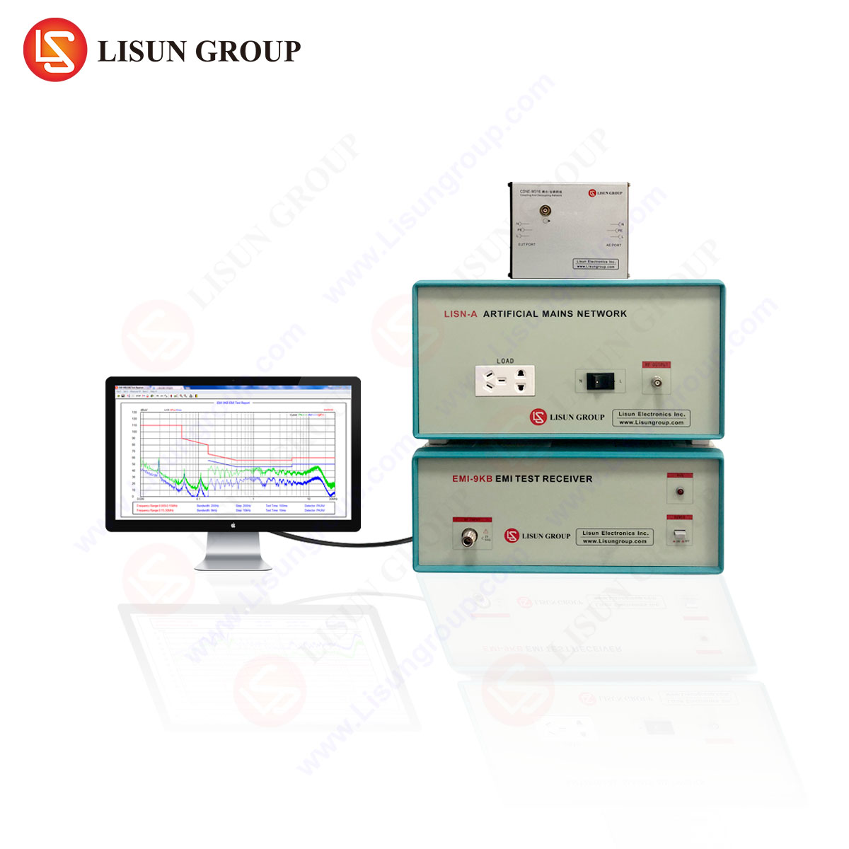
The performance of an EMC chamber is ultimately realized through the accuracy of its measurement instrumentation. The EMI receiver is the core device for emissions testing, converting captured electromagnetic signals into quantifiable data. The LISUN EMI-9KB EMI Receiver exemplifies the technological precision required for modern compliance testing.
The EMI-9KB operates on the principle of heterodyne reception, employing a preselection filter, a mixer, an intermediate frequency (IF) amplifier, and a detector to measure RF signals from 9 kHz to 9 GHz. Its design adheres strictly to the CISPR 16-1-1 standard for radio disturbance and immunity measuring apparatus. Key specifications that define its utility in a chamber environment include an amplitude measurement range of -127 dBm to +20 dBm, a built-in preamplifier with a low noise figure, and a high absolute amplitude accuracy of ± 1.5 dB. Its real-time bandwidth of up to 10 MHz enables efficient detection of transient emissions from Электроинструменты or switching Энергетическое оборудование.
Table 1: Key Specifications of the LISUN EMI-9KB EMI Receiver
| Parameter | Specification |
| :— | :— |
| Frequency Range | 9 kHz – 9 GHz |
| Measurement Range | -127 dBm to +20 dBm |
| IF Bandwidths | 200 Hz, 9 kHz, 120 kHz, 1 MHz, 3 MHz, 10 MHz (CISPR, MIL-STD) |
| Detector Types | Peak, Quasi-Peak, Average, RMS-Average |
| Absolute Amplitude Accuracy | ± 1.5 dB |
| Real-Time Analysis Bandwidth | Up to 10 MHz |
| Interface | LAN, GPIB, USB |
The receiver supports all mandatory detector functions: Peak, Quasi-Peak (QP), Average (AV), and RMS-Average. The QP detector, with its defined charge and discharge time constants, is particularly crucial for assessing the subjective annoyance of repetitive impulsive interference from Бытовая техника или Осветительные приборы with switching drivers. The instrument’s scanning speed and accuracy directly impact testing throughput, a critical economic factor for test laboratories servicing the Оборудование информационных технологий и Электронные компоненты sectors.
Chamber Validation and Calibration Procedures
Prior to operational use, an EMC testing chamber must undergo a series of validation tests to certify its conformance to international standards. The primary tests are Normalized Site Attenuation (NSA) and Field Uniformity (FU).
NSA validation, per ANSI C63.4 or CISPR 16-1-4, involves transmitting a known signal between two antennas at specified locations within the chamber and comparing the measured attenuation to theoretical values. Deviations must fall within ±4 dB tolerance across the frequency range to confirm the chamber’s suitability for radiated emissions testing. For a chamber targeting Аудио-видео оборудование testing up to 6 GHz, this validation ensures that reflections do not artificially amplify or nullify emissions from the EUT.
FU validation, per IEC 61000-4-3, is critical for radiated immunity testing. A field probe is used to measure the generated field strength across a uniform area grid (typically 1.5m x 1.5m) at multiple frequencies. A uniformity of 0 dB to +6 dB across 75% of the grid points is required to ensure the EUT is exposed to a known, consistent stress field, which is vital for reliably testing the immunity of Медицинские приборы или Интеллектуальное оборудование control systems.
Application-Specific Testing Configurations and Industry Use Cases
The configuration of the EUT, its cabling, and auxiliary equipment within the chamber is standardized to ensure reproducibility. For conducted emissions testing (e.g., CISPR 14-1 for Бытовая техника), a Line Impedance Stabilization Network (LISN) is placed on the ground plane to provide a standardized impedance for measuring noise on the power mains. For radiated emissions, the EUT is placed on a non-conductive table at a standard height, with cables draped in a specified manner over the ground plane edge.
In the Автомобильная промышленность, components are tested per CISPR 25 and ISO 11452-2, often using a stripline or TEM cell inside a chamber for lower frequency immunity. Железнодорожный транзит equipment follows EN 50121, requiring testing for both high-frequency emissions and low-frequency magnetic field immunity. For Осветительные приборы with LED drivers, the focus is on broadband noise from switching frequencies, measured using the EMI-9KB’s peak and average detectors from 150 kHz to 30 MHz. The EMI-9KB’s wide dynamic range is essential when testing Энергетическое оборудование, where high-amplitude fundamental frequencies must be measured alongside low-level harmonic emissions without overloading the receiver’s input stage.
Advanced Chamber Features for Future-Proof Testing
Emerging technologies demand continuous evolution of chamber capabilities. Testing for Космический корабль and high-frequency Передача сообщений (e.g., 5G mmWave) pushes the upper frequency limit, requiring absorbers effective at 40 GHz or higher and receivers like the EMI-9KB with a 9 GHz upper bound. Automotive radar testing at 77-81 GHz necessitates even more specialized chambers. The integration of fully automated antenna masts, turntables, and measurement software, often controlled via LAN by instruments like the EMI-9KB, enhances efficiency and eliminates operator error. Furthermore, chambers designed for Медицинские приборы may incorporate additional safety interlocks and monitoring for patient-connected equipment during immunity testing.
Заключение
EMC testing chambers are sophisticated scientific instruments, not merely rooms. Their design, validation, and operation are governed by precise engineering principles and international standards. The correlation between chamber performance—defined by its shielding, absorption, and site attenuation—and the accuracy of the measurement instrumentation within it is absolute. A chamber of exemplary design cannot yield compliant data with an inferior receiver, and conversely, a precision instrument like the LISUN EMI-9KB EMI Receiver cannot perform to its specification in an unvalidated or poorly constructed environment. For manufacturers across the spectrum from Низковольтные электроприборы to Инструментарий, investing in or utilizing test facilities that harmonize advanced chamber infrastructure with calibrated, standards-compliant measurement technology is the definitive pathway to achieving robust product compliance, ensuring operational reliability, and securing global market access.
Часто задаваемые вопросы (FAQ)
Q1: What is the significance of the Quasi-Peak detector in the EMI-9KB, and when is it required?
The Quasi-Peak detector weights signals based on their repetition rate, modeling the human auditory response to interference. It is a mandatory detector for most commercial emissions standards (CISPR). It is particularly important for assessing repetitive noise from switched-mode power supplies in Бытовая техника или Осветительные приборы, as it determines if the emission characteristic is likely to cause objectionable radio interference.
Q2: Can a single Semi-Anechoic Chamber be used for both emissions and immunity testing?
Yes, a properly characterized SAC can be used for both, provided it meets the respective validation criteria. For emissions, it must pass NSA requirements. For immunity, it must be equipped with field-generating antennas and amplifiers and pass the Field Uniformity test. The chamber’s infrastructure, including filter banks and monitor antenna ports, must support both configurations. The EMI-9KB would be used for the emissions validation and pre-/post-test verification of the immunity field.
Q3: How does the real-time bandwidth of the EMI-9KB benefit testing efficiency?
A wide real-time bandwidth (up to 10 MHz on the EMI-9KB) allows the receiver to capture and analyze a broader swath of the frequency spectrum simultaneously during a sweep. This dramatically reduces total scan time, especially when performing pre-compliance diagnostics or troubleshooting across wide frequency ranges, which is common for complex Оборудование информационных технологий или Передача сообщений devices.
Q4: What are the critical factors when selecting an EMC test chamber for large industrial systems?
Primary factors include physical dimensions to accommodate the EUT with proper clearance, shielding effectiveness at the relevant frequencies (including low frequencies for Промышленное оборудование with high-power drives), ground plane current carrying capacity, and the capacity of the chamber’s power line filters to handle the EUT’s current draw. The measurement system, such as the EMI-9KB, must also have sufficient amplitude headroom to not be overloaded by strong ambient signals from the large EUT.
Q5: Why is chamber validation an ongoing requirement, not a one-time event?
The performance of an EMC chamber can degrade over time due to physical damage to absorbers or shielding, corrosion on mating surfaces of doors, or wear on finger stock gaskets. Periodic re-validation (typically annually or after any significant modification) per standards such as ANSI C63.4 or IEC 61000-4-3 is essential to maintain the accredited status of a test laboratory and ensure the continued integrity of all compliance data generated within the facility.
 English
  Spanish
  Russian
  Portuguese
  Turkish
  Arabic
  German
  Polish
  Italian
  French
  Korean
  Japanese
  Indonesian