

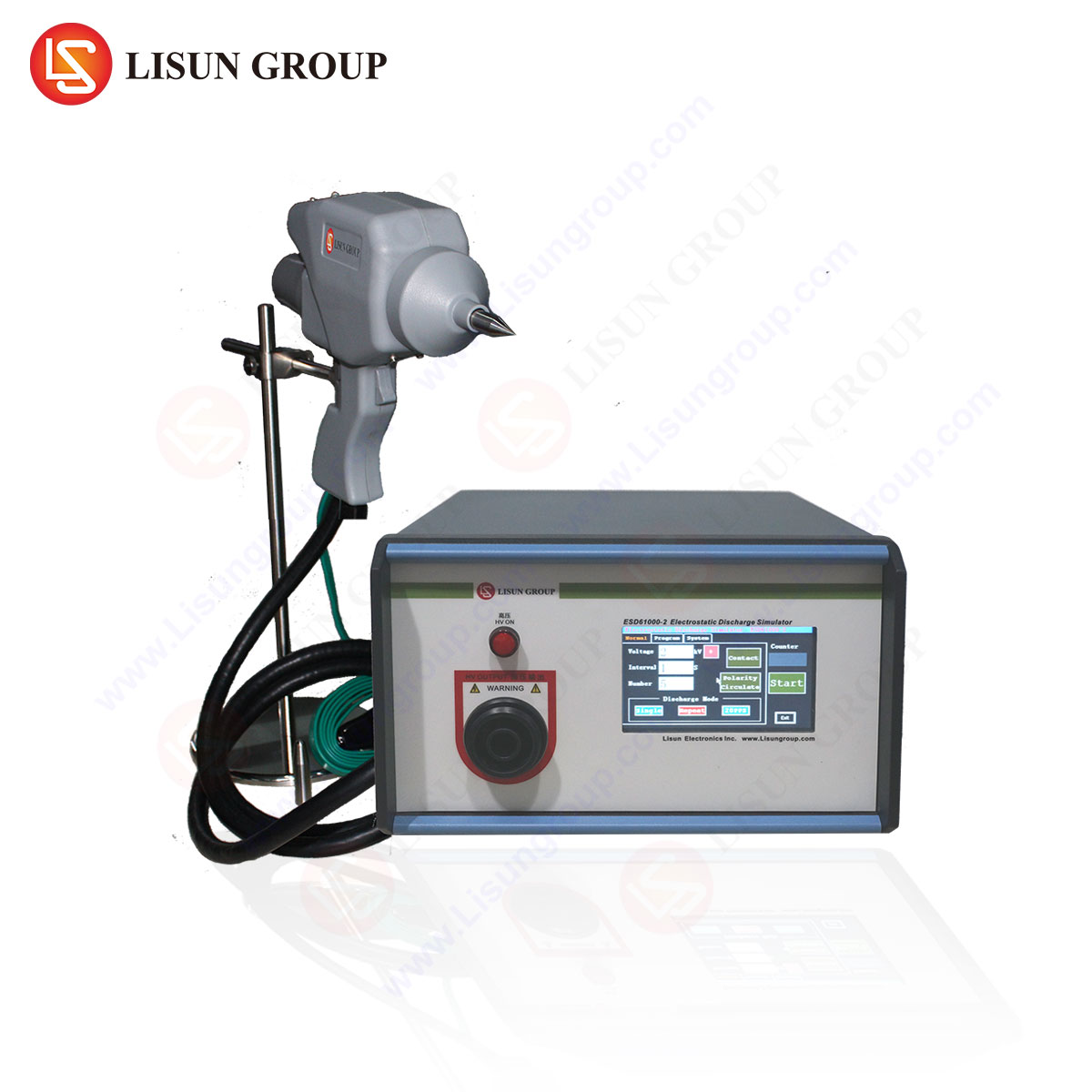



Technical Article Title: Burst Surge Test Guide for IEC 61000-4-4: Methodology, Application, and Implementation with the LISUN SG61000-5 서지 발생기
Introduction: The Imperative of Electrical Fast Transient (EFT) Immunity Testing
The proliferation of electronic control systems across industrial, commercial, and residential domains has necessitated rigorous electromagnetic compatibility (EMC) verification. Among the most pernicious disturbances are electrical fast transients (EFTs), commonly referred to as burst surges. These high-voltage, high-frequency pulses originate from switching operations—such as relay contact arcing, thyristor commutation, or motor brush sparking—and can induce logic errors, data corruption, or physical damage in susceptible circuitry. The International Electrotechnical Commission (IEC) standard 61000-4-4 establishes the framework for evaluating immunity to such phenomena. This guide delineates the technical underpinnings of burst surge testing, the operational principles of the LISUN SG61000-5 Surge Generator, and practical considerations for compliance in diverse equipment categories.
1. Phenomenology of Electrical Fast Transients and Coupling Mechanisms
Electrical fast transients are characterized by a rapid rise time (5 ns ± 30%) and a relatively short pulse duration (50 ns ± 30% at 50% amplitude), repeated in bursts at a repetition rate of 5 kHz or 100 kHz depending on the test level. The burst duration is typically 15 ms, with a 300 ms repetition period. These parameters simulate the spectral content of switching transients encountered in real-world environments.
The disturbances couple into victim equipment through three primary paths: galvanic (direct conduction via power or signal lines), capacitive (electric field coupling to nearby conductors), and inductive (magnetic field coupling due to high di/dt). The standard defines test levels from Level 1 (0.5 kV) to Level 4 (4 kV) for power ports, with corresponding levels for signal, control, and I/O ports. For example, industrial equipment in a heavy industrial environment typically requires Level 4 testing (2 kV for signal lines, 4 kV for power lines). Equipment for residential or office environments—such as lighting fixtures, household appliances, and audio-video equipment—commonly mandates Level 2 (1 kV) or Level 3 (2 kV).
2. The LISUN SG61000-5 Surge Generator: Architecture and Specification Compliance
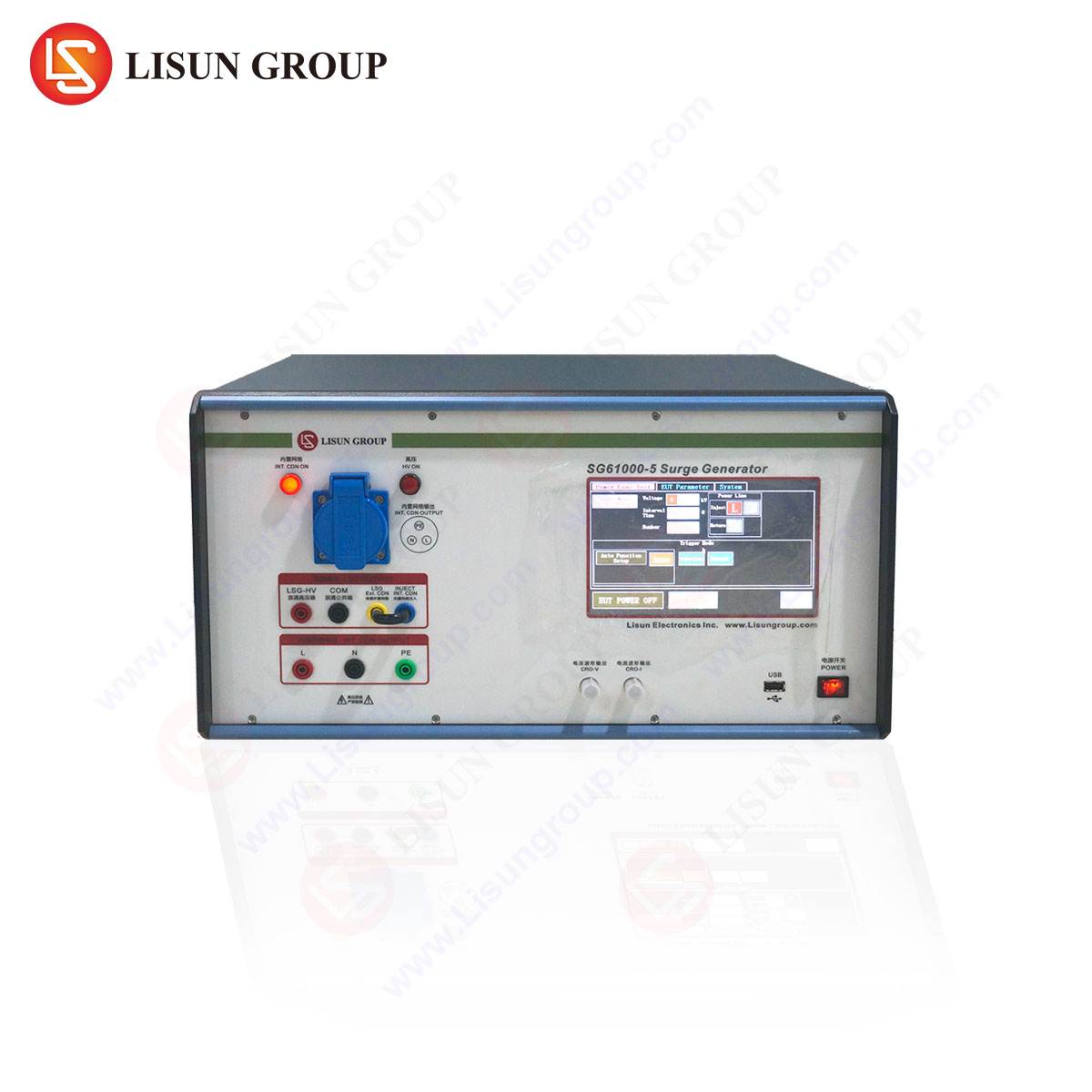
The LISUN SG61000-5 Surge Generator is engineered to deliver precise, repeatable EFT waveforms in full compliance with IEC 61000-4-4 Edition 3.0. Its core architecture integrates a high-voltage DC power supply, a pulse forming network (PFN), a high-speed switching element, and a coupling/decoupling network (CDN) for each test mode.
Key specifications of the LISUN SG61000-5 include:
- Output Voltage Range: 0.2 kV to 4.4 kV (peak, into 50 Ω load), with fine resolution of 10 V steps.
- Rise Time (tr): 5 ns ± 30% (into 50 Ω load).
- Pulse Duration (td): 50 ns ± 30% (at 50% amplitude, into 50 Ω load).
- Burst Repetition Rate: 5 kHz / 100 kHz selectable.
- Burst Duration: 15 ms ± 20%.
- Burst Period: 300 ms ± 20%.
- Polarity: Positive and negative, switchable.
- Internal Coupling Modes: Capacitive coupling (33 nF for power lines), direct injection for I/O lines.
- Phase Angle Control: Synchronization with AC mains (0° to 360°, 1° resolution) and DC level injection.
The generator utilizes a solid-state, high-voltage MOSFET switch to achieve the required switching speed and waveform integrity. Internal impedance is 50 Ω, matching the standard’s requirement for a source impedance of 50 Ω per phase line.
Table 1: Standard Test Level Correspondence (Power Port, 5 kHz)
| Test Level | Open Circuit Voltage (kV) | Repetition Rate | Application Environment (Typical) |
|---|---|---|---|
| 1 | 0.5 | 5 kHz | Well-protected, controlled environments (e.g., medical devices in shielded rooms) |
| 2 | 1.0 | 5 kHz | Residential/office (household appliances, IT equipment) |
| 3 | 2.0 | 5 kHz | Commercial/light industrial (industrial equipment, power tools) |
| 4 | 4.0 | 5 kHz | Heavy industrial/outdoor (rail transit, power equipment, spacecraft subsystems) |
| x | Special (per specification) | 100 kHz (optional) | Custom (e.g., automotive, specific OEM requirements) |
3. Coupling Methods and Network Configuration for Diverse Port Types
The efficacy of a burst surge test hinges on appropriate coupling to the equipment under test (EUT). The LISUN SG61000-5 provides three standardized coupling methods, selectable via a front-panel rotary switch:
-
Capacitive Clamp (IEC 61000-4-4, Section 6.3.2): Used for unshielded signal, control, and data lines. The clamp comprises a metal blade with a 33 nF capacitance per line, allowing the fast transient to couple onto the cable without galvanic contact. This method is critical for testing communication transmission lines, audio-video equipment, and intelligent equipment interfaces.
-
Direct Coupling via Coupling/Decoupling Network (CDN): Employed for AC and DC power ports. The CDN inserts a 33 nF capacitor between the generator output and each phase conductor (L1, L2, L3, N) while providing decoupling inductors to prevent the transient from back-feeding into the mains supply. The LISUN SG61000-5’s internal CDN supports single-phase (2-wire) and three-phase (4-wire) systems up to 32 A per phase.
-
Direct Injection (50 Ω termination): Used for shielded cables or when specific coupling requirements exist. The generator output is connected directly to the test point via a 50 Ω coaxial cable. This is typical for testing electronic components, low-voltage electrical appliances, and instrumentation.
Phase Angle Synchronization: For AC-powered equipment, synchronization of burst injection with the mains waveform is essential. The LISUN SG61000-5 enables precise phase angle selection (0° to 360°), allowing testing at voltage zero-crossing (peak di/dt) or peak voltage (maximum stress). For example, zero-crossing injection is critical for power equipment containing rectifiers or triac circuits, as the high di/dt at zero crossing can trigger false commutation.
4. Test Procedure and Acceptance Criteria for IEC 61000-4-4 Compliance
A systematic test procedure ensures repeatable and meaningful results. The following protocol is recommended for use with the LISUN SG61000-5:
Step 1: Environmental Conditioning. The EUT must be operated under nominal conditions (temperature, humidity, supply voltage) as specified by the manufacturer. For medical devices, reference the relevant product standard (e.g., IEC 60601-1-2).
Step 2: Preliminary Performance Verification. Perform a functional test of the EUT before injection to establish baseline performance criteria (e.g., no data errors, no flicker, no audible disturbances).
Step 3: Generator Calibration. Using a calibrated oscilloscope (1 GHz bandwidth, 50 Ω input), verify the output waveform at the CDN output port. The LISUN SG61000-5 includes a self-calibration loop and a front-panel BNC monitor output for waveform integrity checking.
Step 4: Injection Sequence. Apply bursts at a minimum of 60 seconds per test point, alternating polarities (positive and negative). For power ports, test each phase-to-earth and phase-to-phase combination. For signal ports, test via capacitive clamp or direct injection at the specified level.
Step 5: Performance Criterion Assessment. The standard defines four performance criteria (A, B, C, D). For acceptance in most industries (lighting fixtures, industrial equipment, information technology equipment):
- Criterion A: No degradation of performance during or after testing.
- Criterion B: Temporary degradation (e.g., image disturbance, data loss) that is self-recoverable after testing without operator intervention.
- Criterion C: Degradation requiring operator reset or manual intervention.
- Criterion D: Permanent damage or non-recoverable failure (unacceptable).
5. Application-Specific Testing Scenarios Across Industries
The LISUN SG61000-5 is deployed across a broad spectrum of sectors, each with unique immunity requirements:
-
Lighting Fixtures (LED Drivers, Ballasts): EFT testing at Level 3 (2 kV) on AC mains input. Failure modes include flicker, color shift, or driver shutdown. The SG61000-5’s ability to test at 100 kHz (standard option) is beneficial for high-frequency switching LED drivers.
-
Industrial Equipment (PLC, Motor Drives, Sensors): Typically Level 4 (4 kV) on power ports and Level 3 (2 kV) on I/O lines. The capacitive clamp is essential for testing sensor cables exposed to motor noise.
-
Household Appliances (Refrigerators, Washing Machines, Microwaves): Level 2 (1 kV) on power lines. Coupling via CDN ensures that the transient is injected while the appliance operates on a heater cycle or motor start.
-
Medical Devices (Patient Monitors, Infusion Pumps, Diagnostic Equipment): Strict adherence to IEC 61000-4-4 and IEC 60601-1-2, typically Level 2 or Level 3. The generator’s phase angle control is critical for testing during specific grid voltage phases to simulate worst-case interference.
-
Automobile Industry (ECUs, Inverters, Sensors): IEC 61000-4-4 Level 3 or 4, often combined with the 100 kHz repetition rate to simulate high-frequency switching from DC-DC converters. Direct injection via 50 Ω termination is common for shielded harnesses.
-
Spacecraft Subsystems (Power Distribution Units, Telemetry Modules): Testing at Level 4 with waveform monitoring via the SG61000-5’s monitor output to correlate with radiated susceptibility requirements.
-
Rail Transit (Traction Control, Signaling, Passenger Information Systems): Level 4 with burst duration potentially extended per railway-specific standards (e.g., EN 50121). The generator’s ability to handle 32 A continuous current meets the requirements for rolling stock auxiliary power.
6. Competitive Advantages of the LISUN SG61000-5 in Compliance Testing
When selecting a burst 서지 발생기 for regulatory compliance, the LISUN SG61000-5 offers distinct technical advantages over alternative equipment:
-
Waveform Integrity at High Voltage: Proprietary pulse shaping network ensures rise time (5 ns) and pulse duration (50 ns) remain within tolerance (±30%) even at 4.4 kV output, mitigating overshoot and ringing that can invalidate test results.
-
Integrated Multi-Standard Capability: Beyond IEC 61000-4-4, the SG61000-5 supports testing per IEC 61000-4-5 (surge) and IEC 61000-4-11 (voltage dips) with optional modules, reducing equipment footprint and cost for comprehensive EMC labs.
-
Automated Repetition Sequencing: Programmable burst count, interval, and step progression enable unattended test campaigns. For example, an engineer can sequence Level 1 to Level 4 automatically across all phases and polarities, logging results for auditing.
-
User Interface and Data Logging: The color touchscreen display provides real-time voltage, current, and impedance monitoring. USB and Ethernet ports facilitate export of test reports in CSV or PDF format, a requirement for ISO 17025-accredited laboratories.
-
Safety and Protection: Overvoltage, overcurrent, and thermal shutdown protect both the generator and the EUT. The CDN includes fusing for each phase to prevent secondary fault escalation.
7. Data Interpretation and Common Failure Mitigation Strategies
Analyzing EFT failures is a systematic process. The following table correlates common failure modes with mitigation strategies, applicable across the industries referenced.
Table 2: EFT Failure Analysis and Remediation
| Observed Failure (Criterion B/C) | Likely Coupling Path | Common Affected Component | Mitigation Strategy |
|---|---|---|---|
| Microcontroller reset or data corruption | Capacitive (I/O lines) | Digital logic input pins | Add ferrite bead (100 MHz impedance > 100 Ω) in series; integrate TVS diode (5 V, 200 pF) |
| LED driver flicker | Galvanic (power line) | Switching MOSFET gate drive | Insert common-mode choke (1 mH, 5 A) on AC input; increase gate drive impedance |
| Sensor output drift | Inductive (harness) | Analog front-end (op-amp) | Shielded twisted pair cable; add RC snubber (100 Ω, 10 nF) across input terminals |
| Power supply latch-up | Galvanic (DC input) | Voltage regulator IC | Increase input capacitance (100 µF, low ESR); add series inductor (10 µH) |
8. Calibration and Maintenance Considerations for the SG61000-5
To maintain traceability and compliance, the LISUN SG61000-5 requires periodic calibration per the manufacturer’s schedule (annually recommended). Calibration verifies:
- Open-circuit voltage amplitude (using a high-voltage probe with 100× attenuation, 400 MHz bandwidth).
- Rise time and pulse duration (using a 1 GHz oscilloscope, 50 Ω pass-through).
- Burst repetition rate and duration (time interval measurement).
- Coupling capacitor value (33 nF ± 20% at 1 kHz) and insulation resistance (> 1 GΩ at 500 V DC).
The generator’s self-diagnostic routine, accessible via the maintenance menu, performs a quick check of the HV supply, switching circuit, and CDN integrity before each test series.
9. Future Trends: Adaptive Burst Testing and Higher Repetition Rates
The evolving complexity of power electronics—particularly in rail transit and spacecraft—has driven the need for extended test parameters. The IEC 61000-4-4:2012 Edition 3 introduced the optional 100 kHz repetition rate to simulate transients from modern switch-mode power supplies. The LISUN SG61000-5 natively supports both 5 kHz and 100 kHz bursts. Emerging research suggests that burst durations beyond 15 ms may be necessary for equipment with large DC link capacitors. Although not yet codified, the SG61000-5’s programmable burst duration (adjustable via firmware) allows users to explore these advanced test scenarios for R&D purposes.
자주 묻는 질문
Q1: What is the difference between a burst surge (IEC 61000-4-4) and a combinational surge (IEC 61000-4-5)?
A: The burst surge is a high-frequency (5 ns rise time), low-energy (millijoules per pulse) waveform repeated in bursts, simulating switching transients. The combinational surge (8/20 µs current, 1.2/50 µs voltage) is a high-energy (kilojoules) single pulse simulating lightning-induced overvoltages. The LISUN SG61000-5 can be configured with an optional module to perform both tests.
Q2: Can the LISUN SG61000-5 test three-phase equipment above 32 A?
A: The standard internal CDN is rated for 32 A per phase. For equipment with higher current draw (e.g., 63 A industrial drives), an external CDN or coupling clamp must be used. The SG61000-5’s output can drive external CDN units up to 100 A.
Q3: How do I select the correct repetition rate (5 kHz vs. 100 kHz) for my product?
A: For products operating below 1 MHz switching frequency (e.g., traditional relays, line-frequency transformers), 5 kHz is appropriate. For equipment with PWM frequencies above 50 kHz (e.g., modern DC-DC converters, LED drivers, automotive inverters), use 100 kHz. Refer to your product standard (e.g., IEC 61347-1 for lighting) for definitive guidance.
Q4: What is the recommended setup for testing a medical device with grounded enclosure?
A: Connect the EUT’s protective earth (PE) terminal to the SG61000-5’s PE reference bar via a low-inductance strap (thickness > 2 mm, width > 20 mm). Inject bursts between each phase and PE using the CDN. For patient-connected cables, use a capacitive clamp with the generator output set to Level 2 (1 kV) as per IEC 60601-1-2.
Q5: My product fails Criterion B during burst testing. What is the first investigation step?
A: Isolate the failing port by testing power and signal lines separately. Use a near-field probe connected to an oscilloscope to identify which PCB trace or component node exhibits the highest induced voltage. Common suspects include long traces connecting to connectors, unshielded crystal oscillators, and reset line paths.
 English
  Spanish
  Russian
  Portuguese
  Turkish
  Arabic
  German
  Polish
  Italian
  French
  Korean
  Japanese
  Indonesian