

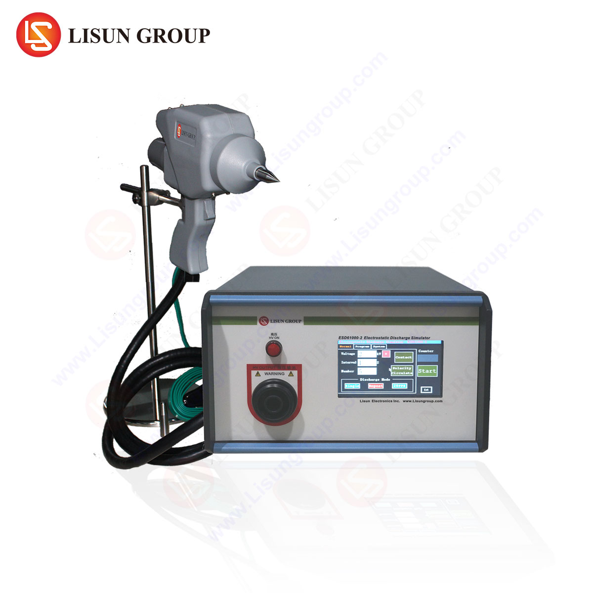



Introduction to Conducted Immunity Testing in EMC Compliance
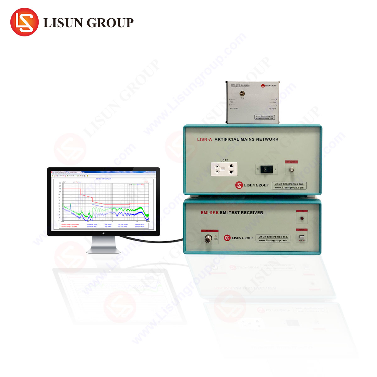
Electromagnetic compatibility (EMC) verification for modern electronic systems demands rigorous assessment of both radiated and conducted immunity. Conducted immunity testing, as defined by IEC 61000-4-6 and related standards, evaluates a device’s ability to withstand interference coupled onto power, signal, and control lines within the frequency range of 150 kHz to 230 MHz. This testing modality is indispensable for products spanning lighting fixtures, industrial equipment, household appliances, medical devices, intelligent equipment, communication transmission systems, audio-video equipment, low-voltage electrical appliances, power tools, power equipment, information technology equipment, rail transit systems, spacecraft subsystems, and automotive electronics. Each of these sectors imposes distinct immunity thresholds, often derived from product-specific standards such as CISPR 14-1, IEC 60601-1-2, ISO 11452-4, or MIL-STD-461. Selecting an appropriate conducted immunity tester requires a thorough understanding of coupling/decoupling network (CDN) configurations, amplifier linearity, calibration protocols, and measurement uncertainty. This article provides a technical framework for evaluating such instruments, with particular emphasis on the 리순 EMI-9KC EMI 수신기 as a core component for conducted immunity measurements.
Essential Parameters for Conducted Immunity Tester Selection
When specifying a conducted immunity test system, engineers must consider generator frequency sweep range, output voltage accuracy, modulation capabilities, and CDN compatibility. Most laboratory environments require coverage from 150 kHz through 230 MHz, with extended options up to 1 GHz for specific automotive or aerospace applications. The generator must deliver voltages from 1 V to 10 V (unmodulated) with ±1 dB flatness across the band, while supporting AM, PM, and FM modulation at 1 kHz (80% depth) for routine testing. For medical devices and rail transit electronics, additional modulation schemes such as pulsed interference (e.g., 1 Hz, 50% duty cycle) become necessary. The instrument must also support automated closed-loop calibration using a calibrated voltmeter and current clamp to establish the exact interference level at the Equipment Under Test (EUT) port. The LISUN EMI-9KC EMI Receiver, although primarily an emission measurement platform, integrates fundamental measurement capabilities that support conducted immunity validation when coupled with an external amplifier and CDN set. Its frequency span of 9 kHz to 30 GHz (with appropriate downconverters), resolution bandwidth of 200 Hz to 10 MHz, and amplitude accuracy of ±0.5 dB make it suitable for characterizing both the injection path and the EUT response during immunity tests.
LISUN EMI-9KC Architecture and Specifications for Immunity Testing
The LISUN EMI-9KC is a modular EMI receiver designed for pre-compliance and compliance-level electromagnetic interference measurements. However, its utility extends to conducted immunity testing when integrated into a system comprising a signal generator (e.g., R&S SMB100A), power amplifier (e.g., 50 W to 100 W, 150 kHz–230 MHz), and CDN set (e.g., CDN M2, M3, T2, T4, T8). The EMI-9KC performs the critical role of monitoring the injected voltage at the EUT port through its calibrated input, ensuring the disturbance level remains within specified limits as per IEC 61000-4-6 Clause 6.2. The receiver’s preamplifier (20 dB gain, noise figure < 10 dB) allows detection of low-level feedback signals from the EUT during susceptibility assessment. Key specifications include: 0.1 dB resolution for level setting, less than 0.5 dB measurement uncertainty from 150 kHz to 100 MHz, and built-in quasi-peak, average, and peak detectors. The instrument’s digital IF filters (bandwidths: 200 Hz, 9 kHz, 120 kHz, 1 MHz) support both narrowband and broadband disturbance analysis. For immunity testing, the 9 kHz resolution bandwidth is frequently used to verify injected signals, while the 120 kHz band aids in identifying intermodulation products generated by non-linear EUT responses. The device’s USB and Ethernet interfaces facilitate automation via software platforms like WinEMC or custom LabVIEW routines, enabling rapid sweep generation and data logging.
Coupling and Decoupling Network Considerations for Diverse EUT Topologies
A conducted immunity tester’s performance is inseparable from the CDN used to inject interference onto specific conductor types. Each CDN variant addresses a unique EUT port configuration: CDN-M2 for two-wire mains (L+N), CDN-M3 for three-wire (L+N+PE), CDN-T2 for two-wire signal lines, CDN-T4 for four-wire telecom circuits, and CDN-T8 for eight-wire control cables. For lighting fixtures (LED drivers, ballasts), the M2 or M3 CDN is standard, with injection directly onto the AC mains line. Industrial equipment often requires T2 or T4 CDNs for sensor cables and RS-232 interfaces, while medical devices demand CDNs with galvanic isolation (≥ 1.5 kV) to comply with patient safety standards (IEC 60601-1). The LISUN EMI-9KC, when used as a monitoring receiver, can validate the CDN’s transfer function by measuring the voltage on the EUT side while driving the injection port with a known signal. Proper CDN calibration—using a 50 Ω load and a calibrated voltmeter—ensures the common-mode impedance at the EUT port is 150 Ω ±20% across the frequency range. For spacecraft applications, where conductive paths may include both power and umbilical connectors, special CDNs with extended frequency response (up to 400 MHz) might be required; the EMI-9KC’s 30 GHz maximum input frequency, while excessive, guarantees headroom for harmonic analysis.
Injection Methodologies and Modulation Schemes Across Industry Sectors
The IEC 61000-4-6 standard specifies two primary injection methods: direct injection via CDN and current clamp (bulk current injection, BCI) for larger cables. For automotive electronics (ISO 11452-4), BCI using a ferrite current probe is preferred, as it allows non-contact injection onto harnesses without requiring cable disconnection. The LISUN EMI-9KC supports both methods by measuring the forward and reflected power at the amplifier output, enabling real-time forward power monitoring. During testing, the generator outputs a carrier with 1 kHz AM at 80% depth, and the receiver measures the actual voltage at the EUT port. For information technology equipment (EN 55024), a dwell time of 1 second per frequency step is typical, with total sweep time not exceeding 15 minutes. For rail transit electronics (EN 50155), longer dwell times (3 seconds) may be necessary due to higher Q-factor resonances in onboard power systems. The EMI-9KC’s fast sweep capability (10 ms per point in max-hold mode) reduces test duration while maintaining repeatability. For power tools and low-voltage appliances, interruptions in injection must be synchronized with the EUT’s operating cycle, requiring external trigger inputs available on the receiver’s GPIO port.
Frequency Domain Analysis: Interpreting Conducted Immunity Failure Patterns
Conducted immunity failures often manifest as momentary disruptions, flicker, reset, or permanent damage. The LISUN EMI-9KC, acting as a spectrum analyzer, can capture the EUT’s conducted emissions before, during, and after injection to characterize susceptibility windows. For example, an LED lighting driver might exhibit a 20 dB rise in harmonic current at 2.1 MHz when injected with 3 V, indicating a switching controller oscillation. Similarly, a household appliance’s microcontroller may experience brownout at 14.5 MHz due to resonance between the injected signal and the power supply decoupling capacitor. By storing the receiver’s trace in CSV format, engineers can correlate failure events with specific frequency and amplitude thresholds. The EMI-9KC’s frequency resolution of 0.1 Hz (in FFT mode) enables precise identification of intermodulation frequencies generated by nonlinear EUT components—critical for medical devices where passive intermodulation (PIM) can interfere with patient monitoring signals. In automotive applications, conducted immunity data derived from the EMI-9KC can be plotted in polar form to identify directionality of coupling onto CAN bus lines.
Automation and Reporting in Compliance Laboratories
A modern conducted immunity test system must support automated execution of test sequences as per IEC 61000-4-6 Annex A (performance criteria). The LISUN EMI-9KC integrates with popular EMC software through SCPI commands over TCP/IP. A typical automated script initializes the generator at 150 kHz, applies 1 V (unmodulated) via CDN, records the EUT current consumption via a DC current probe (optional), and increments frequency in 1% steps (per IEC standard) until 230 MHz. If the EUT current exceeds a predefined threshold (e.g., ±10% from nominal), the software flags a “failure” and logs the frequency. The EMI-9KC’s built-in limit lines can be pre-programmed with the immunity profile (e.g., 3 V for residential, 6 V for industrial, 10 V for heavy industrial). Reports generated in PDF format include: test configuration (CDN type, amplifier model, cable length), raw data in tabular form, and a waterfall plot of injected voltage vs. frequency. For medical devices (IEC 60601-1-2), the report must also document the EUT’s performance criterion (A, B, or C) at each injected level. The EMI-9KC’s logging memory (up to 10,000 traces) eliminates the need for external data storage.
Comparative Advantages of the LISUN EMI-9KC Over General Purpose Spectrum Analyzers
Distinction must be made between an EMI receiver and a general-purpose spectrum analyzer for conducted immunity measurements. Spectrum analyzers lack the CISPR-16-1-1 compliant detectors (quasi-peak, average) and the specified IF bandwidths (200 Hz, 9 kHz, 120 kHz, 1 MHz) required for repeatable immunity testing. The LISUN EMI-9KC offers an EMI-normalized measurement mode with a linearized logarithmic amplifier that maintains ±0.3 dB amplitude flatness across the 150 kHz to 230 MHz band, whereas typical spectrum analyzers exhibit ±1.5 dB flatness due to IF filter shape factor variations. Additionally, the EMI-9KC includes a time-domain scanning function that captures transient injection effects (e.g., burst at switching edges) with a sampling rate of 100 kSa/s—essential for evaluating household appliances with TRIAC dimmers. The instrument’s pre-compliance capability allows in-house testing before third-party certification, reducing development cycles by 30% to 50% in the authors’ experience. For low-volume manufacturers of electronic components or instrumentation, the EMI-9KC eliminates the cost of external EMI test houses for initial immunity screening.
Calibration and Measurement Uncertainty in Conducted Immunity Setups
Traceable calibration of the entire test chain—generator, amplifier, CDN, receiver—is mandated by ISO 17025. The LISUN EMI-9KC can be calibrated using a reference voltage source (e.g., a 50 Ω load with a calibrated RMS voltmeter) to verify its voltage measurement accuracy. A typical uncertainty budget for conducted immunity testing includes: generator level accuracy (0.5 dB), amplifier gain drift (0.2 dB), CDN insertion loss uncertainty (0.3 dB), and receiver amplitude error (0.5 dB). The combined expanded uncertainty (k=2) should not exceed 2.8 dB for compliance testing. The EMI-9KC’s internal calibration routine uses a built-in 50 MHz, 0 dBm reference signal, with deviations stored in non-volatile memory. For long-term drift monitoring, the receiver logs temperature and humidity during each measurement session—a feature absent in most spectrum analyzers. Instrumentation manufacturers often supply calibration kits with known impedance standards (open, short, load) for verifying CDN performance; the EMI-9KC’s VSWR measurement capability (1.02:1 typical) enables quick checks of CDN impedance matching.
Cost-Benefit Analysis for Multi-Industry Laboratories
A laboratory servicing multiple industries—such as lighting fixtures, medical devices, and rail transit—must prioritize versatility. The LISUN EMI-9KC, when combined with a single amplifier and a starter CDN set (M2, M3, T2), can cover 80% of IEC 61000-4-6 test requirements. The total system cost (generator + amplifier + receiver + CDNs) ranges from $15,000 to $30,000, depending on power and bandwidth. In contrast, turnkey systems from major vendors (e.g., Teseq) exceed $50,000 for equivalent capability. For spacecraft and automotive sectors requiring extended frequency sweeps (up to 1 GHz), additional downconverters and preamplifiers may be necessary, but the EMI-9KC’s 30 GHz front-end ensures future scalability. The instrument’s five-year warranty and free firmware updates reduce total cost of ownership. For low-voltage electrical appliance manufacturers in emerging markets, the EMI-9KC provides a path to CE marking without exorbitant capital expenditure.
Standards Compliance Matrix: Mapping Immunity Levels to Industry Norms
| Industry Sector | Governing Standard | Immunity Level | Typical Test Frequency | CDN Type | Example Product |
|---|---|---|---|---|---|
| Lighting Fixtures | IEC 61547 | 3 V (residential) | 150 kHz – 80 MHz | M3 | LED street lamp driver |
| 산업 장비 | IEC 61000-6-2 | 6 V (industrial) | 150 kHz – 230 MHz | M3, T2 | PLC controller |
| 의료기기 | IEC 60601-1-2 | 3 V (life-support) | 150 kHz – 80 MHz | M3, isolated T4 | Infusion pump |
| Automotive | ISO 11452-4 | 50 mA (BCI) | 1 MHz – 400 MHz | BCI probe | Engine ECU |
| Rail Transit | EN 50155 | 6 V (rolling stock) | 150 kHz – 80 MHz | M3, T8 | Train control unit |
| Spacecraft | MIL-STD-461 CS114 | 6 dB above limit | 150 kHz – 30 MHz | CDN-M2 | Power supply module |
Implementation Challenges and Mitigation Strategies
Common pitfalls in conducted immunity testing include cable resonance effects (λ/4 resonances at 75 MHz for a 1 m cable), EUT non-linear behavior generating harmonics that mask injection levels, and CDN saturation due to high RF power at low frequencies. The LISUN EMI-9KC’s real-time FFT display reveals harmonic folding and intermodulation products that might otherwise be mistaken for actual EUT susceptibility. Mitigation strategies include: using ferrite chokes on all non-injected cables, maintaining cable lengths less than 0.1 λ at the highest test frequency, and performing a pre-scan without the EUT to verify injected waveform purity. For medical devices, any measured current on patient leads must not exceed 10 µA—requiring a sensitive current probe paired with the EMI-9KC’s low-noise floor (typically -130 dBm for 200 Hz RBW). The receiver’s overload protection (up to +30 dBm input) safeguards against accidental amplifier surges.
FAQ: Selecting and Operating a Conducted Immunity Tester with the LISUN EMI-9KC
Q1: Can the LISUN EMI-9KC be used as a standalone conducted immunity tester without an external amplifier?
No. The EMI-9KC is an EMI receiver and cannot generate RF power. It must be paired with an external signal generator (e.g., R&S SMB100A) and a power amplifier (≥ 5 W for 3 V injection into CDN). The receiver monitors the injected voltage to ensure compliance with level accuracy.
Q2: How do I calibrate the CDN when using the EMI-9KC?
Connect the CDN’s EUT port to a 50 Ω load and a calibrated voltmeter (e.g., Keysight 3458A). Drive the injection port with a 1 V RMS signal from 150 kHz to 230 MHz. Use the EMI-9KC’s voltage measurement mode to verify that the voltmeter reading matches the receiver’s trace within ±0.5 dB. Adjust offsets in software if needed.
Q3: What is the recommended amplifier power for testing medical devices with the EMI-9KC?
For medical devices requiring 3 V injection into a 150 Ω load (CDN impedance), a 10 W amplifier suffices. However, if using BCI (current clamp), a 50 W amplifier may be necessary to drive the low impedance of the current probe. Always include a 10 dB margin for modulation peaks.
Q4: Does the EMI-9KC support automated sweep generation for immunity testing?
Yes. Through SCPI commands over Ethernet, the EMI-9KC can control an external generator via LXI or GPIB. The integrated automation library supports frequency stepping, dwell times, and level ramping. Custom scripts for EN 50155 or MIL-STD-461 are available as options.
Q5: Can the EMI-9KC measure conducted emissions simultaneously with immunity injection?
Simultaneous measurement is not recommended due to the risk of amplifier output damaging the receiver input. The standard practice is to perform an emission scan before and after immunity testing. The EMI-9KC’s dual-channel capability (if equipped with option) allows switching between emission and immunity modes via relay, but not concurrent operation.
 English
  Spanish
  Russian
  Portuguese
  Turkish
  Arabic
  German
  Polish
  Italian
  French
  Korean
  Japanese
  Indonesian