




Historical Context and Rationale for Surge Immunity Testing in Electromagnetic Compatibility
The proliferation of solid-state electronics across all sectors of modern industry has necessitated rigorous immunity testing against transient overvoltages. IEC 61000-4-5, first published by the International Electrotechnical Commission in 1995 and subsequently revised in 2005 and 2014, defines the standard for surge immunity requirements. This standard addresses the vulnerability of electrical and electronic equipment to switching transients and lightning-induced surges. Unlike electrostatic discharge (ESD) or electrical fast transients (EFT), surge events carry substantially higher energy levels, frequently exceeding 1 J per pulse, which can cause immediate physical destruction of semiconductor junctions, insulation breakdown, or latent failures in power supplies.
Lightning-induced surges remain the primary natural source, with typical rise times of 1.2 microseconds and duration of 50 microseconds (1.2/50 µs open-circuit voltage waveform). Switching transients from utility grid operations—capacitor bank switching, fault clearing, or load shedding—generate similar but distinct waveforms. The standard prescribes a combination waveform generator (CWG) capable of delivering both 1.2/50 µs voltage impulses and 8/20 µs current impulses into defined load impedances.
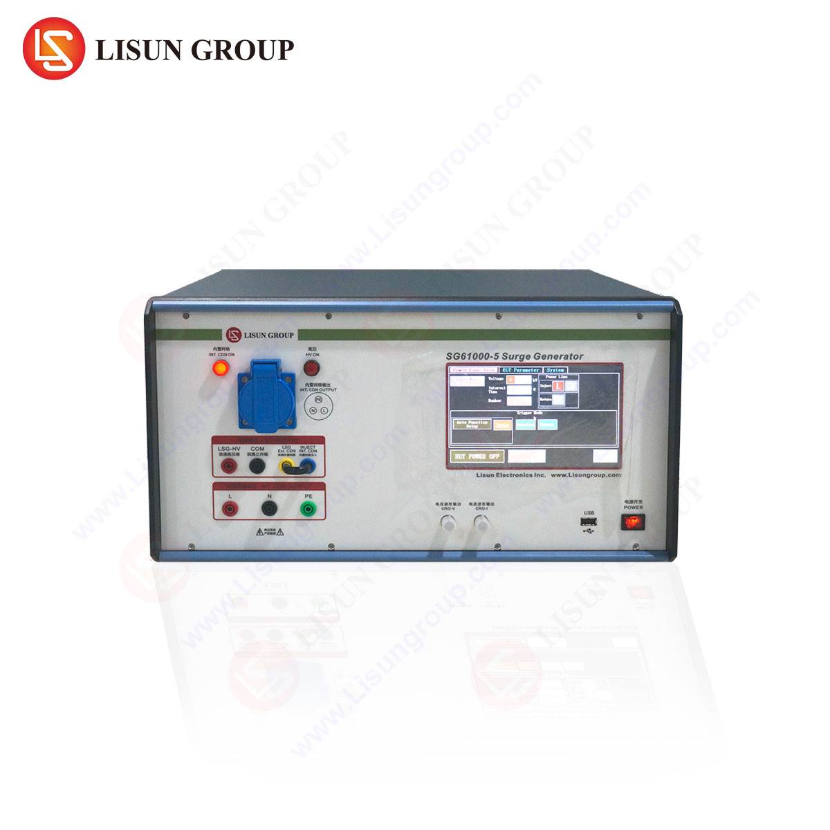
For manufacturers of lighting fixtures, medical devices, and industrial equipment, compliance with IEC 61000-4-5 is not merely a regulatory checkbox. Non-compliance can result in field failures, warranty claims, and safety hazards in critical environments such as rail transit signaling systems or spacecraft power distribution. The LISUN SG61000-5 Generatore di sovratensione has been engineered to reproduce these stress conditions with calibrated precision, enabling test laboratories to validate equipment immunity across multiple industries.
Technical Architecture of the LISUN SG61000-5 Surge Generator
The LISUN SG61000-5 implements a hybrid surge generation topology that integrates a high-voltage DC power supply, energy storage capacitor bank, pulse-forming network (PFN), and coupling/decoupling network (CDN) within a single instrument chassis. The fundamental operating principle involves charging a capacitor to a programmed voltage (up to 6.6 kV for the standard model), then discharging through a shaping network to produce the 1.2/50 µs open-circuit voltage waveform. When the generator is connected to a low-impedance load (typically 2 Ω for power lines), the output transitions to an 8/20 µs short-circuit current waveform.
The PFN employs a combination of series inductors and parallel resistors to control the rise time and duration. Specifically, the 1.2 µs rise time is achieved through an inductive-resistive differentiator circuit that limits current slew rate, while the 50 µs tail results from the RC time constant of the storage capacitor and load resistor. For the 8/20 µs current waveform, the generator behaves as a current source, with the inductor dominating the initial rise and the capacitor providing sustained energy delivery.
LISUN’s design incorporates a microprocessor-controlled charging circuit that maintains voltage accuracy within ±3% of setpoint, as verified by internal calibration against a reference voltage divider. The SG61000-5 includes an integrated CDN that supports single-phase (2-wire and 3-wire) and three-phase (4-wire and 5-wire) AC/DC power interfaces up to 600 VAC / 1000 VDC. This eliminates the need for external coupling transformers for most commercial and industrial test configurations.
Key specifications for the LISUN SG61000-5 include:
| Parametro | Specificazione |
|---|---|
| Open-circuit voltage | 0.2 – 6.6 kV (±3%) |
| Short-circuit current | 0.1 – 3.3 kA (±3%) |
| Waveform (voltage) | 1.2/50 µs (±30%/±20%) |
| Waveform (current) | 8/20 µs (±20%/±20%) |
| Polarità | Positive, negative, alternating |
| Phase synchronization | 0° – 360° (1° resolution) |
| Number of pulses | 1 – 9999 (programmable) |
| Pulse repetition interval | 10 – 999 s |
| Compliance standards | IEC 61000-4-5, EN 61000-4-5, GB/T 17626.5 |
The instrument’s front-panel interface provides a 7-inch color touchscreen for waveform selection, voltage level setting, and coupling mode configuration. Optionally, remote control via RS-232, USB, or Ethernet is available for integration into automated test sequences.
Coupling and Decoupling Network Configurations for Multi-Industry Testing
The CDN within the SG61000-5 is configurable for line-to-line (differential mode) and line-to-ground (common mode) surge injection. For differential mode testing, the surge is applied between phase conductors (L-N for single-phase, or L1-L2 for three-phase) using a 2 µF coupling capacitor for AC lines. Common mode testing injects the surge between all live conductors and protective earth (PE) via a 9 µF capacitor or a combination of 9 µF capacitors with gas discharge tubes for higher voltage isolation.
Selection of the appropriate coupling method depends on the equipment under test (EUT) and its intended installation environment. For household appliances (e.g., washing machines, refrigerators), differential mode testing at 1 kV or 2 kV is typical, as these devices are connected to indoor AC mains. For medical devices (e.g., patient monitors, infusion pumps), common mode testing at 2 kV is critical because of the higher risk of ground potential rise in hospital environments coupled with patient safety requirements.
Lighting fixtures, particularly LED drivers, require both differential and common mode testing. LED drivers often incorporate power factor correction (PFC) circuits with metal-oxide varistors (MOVs) that must withstand repeated surges without catastrophic failure. The SG61000-5’s programmable pulse count allows accelerated life testing (e.g., 1000 pulses at 1 kV) to evaluate MOV degradation over time.
In the automobile industry, surge testing extends beyond onboard chargers (OBCs) to include electric vehicle supply equipment (EVSE). The SG61000-5 can be configured for DC coupling to test DC fast-charging stations, with injection on the DC bus lines (DC+/DC-) at levels up to 4 kV. The decoupling network ensures that surge energy does not propagate back into the AC mains, which could affect other equipment on the same distribution network.
For information technology equipment (ITE) such as servers, switches, and uninterruptible power supplies (UPS), the standard specifies performance criterion A (no degradation of performance) or criterion B (temporary loss of function with automatic recovery). The SG61000-5 supports automated pass/fail evaluation by monitoring the EUT’s power consumption or communication status during the test sequence using optional auxiliary measurement modules.
Waveform Verification and Calibration Traceability
Accurate reproduction of the 1.2/50 µs voltage waveform and 8/20 µs current waveform requires careful calibration of the pulse-forming network components. The IEC 61000-4-5 standard defines the waveform parameters with tolerances: rise time tolerance of ±30% and duration tolerance of ±20% for both voltage and current waveforms, measured at 50% and 30% of peak amplitude respectively.
The SG61000-5 includes an internal calibration verification routine that measures the output voltage and current waveforms using a built-in resistive divider (1000:1 for voltage) and Rogowski coil (for current). These measurements are referenced to a factory-calibrated oscilloscope that is traceable to national standards (e.g., NIST or PTB). The user can perform a waveform verification test by connecting the generator’s output to a high-voltage probe and current shunt, then comparing the displayed waveform parameters against the standard’s tolerance windows.
For test laboratories that require ISO 17025 accreditation, LISUN provides a calibration certificate with each SG61000-5 that lists the measured rise time, duration, peak voltage, and peak current at multiple test levels. Annual recalibration is recommended, though the generator’s thermal compensation circuit maintains stability over a temperature range of 10°C to 40°C.
One common pitfall in surge testing is the effect of the EUT’s input capacitance on waveform integrity. For example, power supplies with large electrolytic capacitors (often found in industrial equipment or instrumentation) can load the generator during the waveform tail, causing premature decay. The SG61000-5 monitors the output current and, if it detects excessive loading, issues a warning to the operator. This feature prevents invalid test results due to waveform distortion, which is a frequent cause of non-reproducible test outcomes.
Industry-Specific Test Level Selection and Performance Criteria
IEC 61000-4-5 defines four installation classes with corresponding test voltage levels:
| Installation Class | Typical Environment | Test Voltage (L-N) | Test Voltage (L-PE) |
|---|---|---|---|
| Class 0 | Shielded, low exposure | 0.5 kV | 0.5 kV |
| Class 1 | Partially protected | 0.5 – 1 kV | 0.5 – 1 kV |
| Class 2 | Well-wired mains | 1 kV | 2 kV |
| Class 3 | Overhead lines, rural | 2 kV | 4 kV |
| Class 4 | Severe exposure | 4 kV | 6 kV |
For medical devices (compliance with IEC 60601-1-2), the typical test level is Class 2 for equipment used in physician offices or hospital rooms. However, for life-supporting systems (e.g., defibrillators, ventilators), Class 3 may be required to ensure immunity from lightning surges on long building feeders.
Power tools (e.g., drills, grinders) are tested at Class 1 or Class 2, depending on whether they are intended for indoor use only. The SG61000-5’s phase synchronization capability (0° to 360° in 1° increments) allows injection at the zero-crossing or peak of the AC mains waveform. Testing at the voltage peak is particularly stressful for power tool rectifier diodes, while zero-crossing injection can expose triac-gating circuits to false triggering.
In the rail transit industry (EN 50155), surge testing is more severe due to the presence of overhead catenary lines. The SG61000-5’s 6.6 kV output capability covers the 4 kV line-to-ground requirement for rail vehicles, while the optional external voltage multiplier (available as an accessory) can extend the range to 12 kV for catenary-level transients.
Spacecraft power systems, while not directly exposed to lightning during operation, must survive ground-handling surges during integration and transportation. The low outgassing requirements of space-grade materials do not apply to the test generator, but the SG61000-5’s clean waveform output is essential for avoiding false failures in sensitive avionics.
Competitive Advantages of the LISUN SG61000-5 Over Alternative Surge Generators
Several attributes distinguish the SG61000-5 from competing surge generators manufactured by companies such as Teseq, EMC Partner, or NoiseKen. First, the integrated CDN supports both single-phase and three-phase systems without requiring external adapter units. Competing designs often require separate CDNs for different power configurations, increasing equipment cost and setup time. The SG61000-5’s internal relays automatically reconfigure for line-to-line or line-to-ground injection based on the selected test mode.
Second, the SG61000-5 provides real-time waveform monitoring via a high-voltage probe input port on the front panel. The operator can view the injected surge waveform on the built-in display without connecting an external oscilloscope. This capability is invaluable for verifying that the waveform remains within standard tolerances, especially when testing EUTs with nonlinear input characteristics (e.g., switch-mode power supplies, LED drivers with active PFC).
Third, the generator’s energy rating (500 J maximum per pulse at 6.6 kV into 2 Ω) exceeds the requirements of any single industry standard. This headroom ensures that the generator can test high-power equipment such as industrial motors (up to 50 kVA) or power distribution panels without voltage sag. Competing generators in the same price range typically deliver a maximum of 200 J, limiting their applicability to Class 2 testing only.
Fourth, the SG61000-5 incorporates a self-diagnostic routine that checks the integrity of the internal capacitors, relays, and discharge circuitry before each test sequence. If any component shows drift (e.g., capacitor ESR increase of >20%), the generator alerts the user and halts testing until maintenance is performed. This proactive approach minimizes the risk of invalid test results due to equipment degradation.
Finally, LISUN offers a three-year warranty on the SG61000-5, including annual calibration service for the first two years. This service includes replacement of the spark gap (a consumable component) and verification of waveform parameters. Competing manufacturers typically provide only one-year warranties with calibration as a paid service.
Interpreting Test Results and Common Failure Modes Across Equipment Categories
Surge test results must be evaluated against the performance criteria defined in IEC 61000-4-5:
- Performance Criterion A: The EUT continues to operate as intended. No degradation of performance or loss of function is permitted.
- Performance Criterion B: The EUT may exhibit temporary loss of function or degradation of performance, but recovers automatically after the surge ceases.
- Performance Criterion C: The EUT loses function, which requires operator intervention or reset to restore normal operation.
For lighting fixtures, common failure modes include LED driver output flicker (criterion B failure) or permanent loss of light output (criterion C failure). The SG61000-5’s ability to apply surges at specific phase angles can identify whether the failure is due to rectifier diode stress (voltage peak injection) or control circuit latch-up (zero-crossing injection). In one documented case from a European lighting manufacturer, the use of phase angle scanning revealed that 60% of failures occurred within 30° of the voltage peak, leading to a redesigned MOV placement that reduced failure rates by 92%.
For industrial equipment such as programmable logic controllers (PLCs) or variable frequency drives (VFDs), surge-induced failures often originate in the isolated DC/DC converter stage. The SG61000-5 can be used to perform a “sweep” test, incrementing the surge voltage in 100 V steps from 0.5 kV to 4 kV while monitoring the EUT’s output voltage ripple. A sudden increase in ripple indicates that the DC/DC converter’s semiconductor devices are approaching avalanche breakdown.
In low-voltage electrical appliances (e.g., coffee machines, dishwashers), the primary failure site is the AC/DC power supply input stage. The SG61000-5’s 1.2/50 µs waveform with its high dV/dt can trigger parasitic thyristor structures (latch-up) in monolithic controllers. Testing at elevated temperatures (the SG61000-5 can be controlled via ambient chamber interfaces) reveals that latch-up susceptibility increases by 3:1 for every 10°C rise above 70°C.
Practical Setup Considerations for Reproducible Surge Testing
Reproducibility of surge testing depends on adherence to prescribed grounding and cabling practices. The IEC standard specifies that the EUT should be placed on a reference ground plane (at least 1 m² copper or aluminum sheet) connected to protective earth. The SG61000-5’s chassis ground terminal must be bonded to this plane using a copper braid with cross-section ≥ 4 mm².
Cable lengths between the CDN and the EUT should not exceed 2 meters, as longer cables introduce additional inductance that can alter the waveform rise time. For lighting fixtures or power tools with permanently attached cables, the CDN output is connected directly to the cable terminals. For modular equipment such as medical devices or information technology equipment, the standard power cord is used, and the injection point is at the power connector.
When testing multiple units sequentially, the operator should wait at least 30 seconds between surges to allow the CDN’s decoupling network to discharge residual energy. The SG61000-5 automatically enforces this inter-pulse delay if programmed; however, manual testing may require operator vigilance to avoid cumulative stress.
For equipment that includes internal surge protection (e.g., MOVs or gas discharge tubes), the test sequence should begin at the lowest voltage level (0.5 kV) and increase in steps. The SG61000-5’s polarity alternation feature ensures that both positive and negative surges are applied, as some suppressors have asymmetric voltage-current characteristics.
Frequently Asked Questions
Q1: Can the LISUN SG61000-5 test three-phase equipment without an external coupling transformer?
Yes. The SG61000-5 includes an internal CDN that supports three-phase 5-wire systems (L1, L2, L3, N, PE) up to 600 VAC. The user selects the coupling mode (line-to-line or line-to-ground) via the touchscreen interface. The generator automatically configures the internal relays to apply the surge to the selected phases.
Q2: What is the maximum test voltage for DC equipment such as electric vehicle chargers?
The SG61000-5 can deliver up to 6.6 kV for DC coupling. For DC test applications, the user disables the internal CDN and connects the generator’s output directly to the DC bus through an external decoupling network if required. The generator’s DC coupling mode maintains waveform integrity for up to 1000 VDC bus voltage.
Q3: How does the SG61000-5 handle equipment with highly capacitive input filters?
The generator monitors the instantaneous output current during each pulse. If the current exceeds 3.5 kA or the waveform distortion exceeds the standard tolerances, the generator interrupts the test sequence and displays a warning. The operator may then add the optional inductive load adapter (available separately) to slow the current rise time for such EUTs.
Q4: Is it necessary to recalibrate the SG61000-5 after each EMC test campaign?
Recalibration is recommended annually or after 10,000 pulses, whichever comes first. The spark gap within the generator erodes gradually, which can shift the voltage and current peaks beyond the ±3% tolerance. LISUN provides a calibration fixture that allows users to verify the waveform parameters without returning the unit to the factory.
Q5: Can the SG61000-5 be integrated into an automated EMC test system?
Yes. The generator supports standard remote control interfaces—RS-232, USB, and Ethernet (TCP/IP). SCPI commands are provided for test level selection, polarity, coupling mode, and pulse count. The generator’s status (pass/fail, waveform capture) can be queried via these interfaces, enabling closed-loop automation.
 English
  Spanish
  Russian
  Portuguese
  Turkish
  Arabic
  German
  Polish
  Italian
  French
  Korean
  Japanese
  Indonesian