




Electromagnetic Compatibility Verification Protocols for Defense-Grade Platforms: A Risk-Informed Approach Using the ليسون EMI-9KC Receiver
خلاصة
The operational integrity of modern defense systems is inextricably linked to their electromagnetic compatibility (EMC). Unlike commercial devices, military platforms—ranging from unmanned aerial vehicles to shipboard radar arrays—operate in spectrally dense and contested environments where electromagnetic interference (EMI) can precipitate mission failure, data corruption, or catastrophic system degradation. This whitepaper delineates a comprehensive EMC test procedure framework tailored for defense applications, integrating the precision measurement capabilities of the LISUN EMI-9KC receiver. The document addresses test environment design, measurement uncertainty, and compliance assessment across diverse subsystems, including spacecraft telemetry, rail transit command links, and secure communication transmission networks. By leveraging the EMI-9KC’s advanced spectral analysis features, test engineers can achieve reproducible, standards-compliant evaluations that meet the stringent requirements of MIL-STD-461 and equivalent defense guidelines.
The Imperative for Spectral Purity in Network-Centric Warfare Systems
Modern defense architectures are no longer monolithic; they comprise interconnected nodes of intelligent equipment, power distribution units, and low-voltage electrical appliances, all coexisting within a constrained electromagnetic envelope. The proliferation of wide-bandgap semiconductors in power equipment and the adoption of high-speed digital buses in information technology equipment have introduced new noise spectra that were previously inconsequential. Unmanaged, these emissions can desensitize communication transmission front-ends or induce false triggering in ordnance initiation circuits.
For the defense sector, EMC testing transcends simple regulatory compliance. It is a risk management exercise aimed at ensuring functional safety under duress. A lighting fixture on a naval vessel, for instance, can generate conducted emissions that propagate through the power bus, disrupting sensitive sonar processing. Similarly, an electronic component within a missile guidance system must exhibit immunity to radiated fields from high-power radar emitters. Consequently, the test procedure must be exhaustive, repeatable, and traceable to national metrology standards. This requires a measurement receiver that offers not only high sensitivity but also the dynamic range necessary to analyze both narrowband clock harmonics and broadband transient disturbances.
LISUN EMI-9KC: Precision Architecture for Defense Frequency Bands
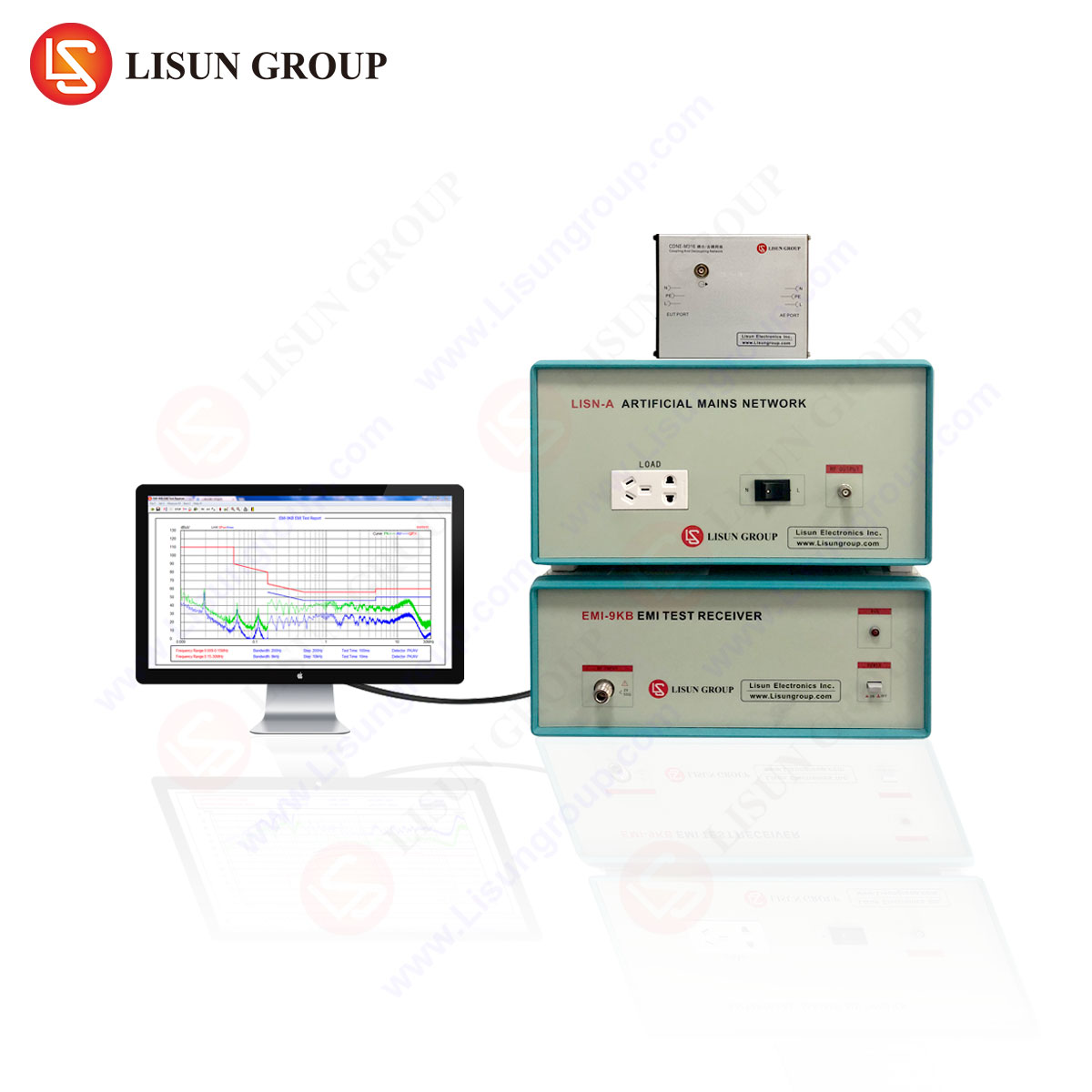
At the core of a robust defense EMC laboratory is the measurement instrument. The LISUN EMI-9KC electromagnetic interference receiver is engineered to function as the primary diagnostic tool for pre-compliance and full-compliance testing per CISPR 16-1-1 requirements, while extending its utility to defense-specific protocols. It is a full-featured receiver that replaces the need for a separate spectrum analyzer and quasi-peak detector, offering a seamless frequency range from 9 kHz to 30 GHz (configurable), which covers the fundamental emissions from switching power supplies in industrial equipment up to the harmonic frequencies of satellite communication links.
Key Technical Specifications and Measurement Principles
The EMI-9KC operates on the principle of a superheterodyne receiver architecture, which provides superior frequency selectivity and sensitivity compared to broadband spectrum analyzers. Its core specifications include:
- نطاق التردد: 9 kHz – 30 GHz (with external mixing for millimeter-wave extensions).
- Detector Modes: Peak, Quasi-Peak, Average, and RMS. The Quasi-Peak detector is crucial for correlating measured interference with the subjective annoyance of communication systems, while the Average detector is essential for evaluating CISPR 16-1-1 compliance for continuous disturbances.
- عرض النطاق الترددي للدقة (RBW): Adjustable from 10 Hz to 1 MHz, allowing for the isolation of discrete signals from broad-spectrum noise.
- النطاق الديناميكي: > 75 dB (typ.), enabling the simultaneous observation of weak signals in the presence of strong in-band interference—a common scenario in congested defense frequency bands.
- EMI Analysis Software: Integrated automation software supports frequency scans, time-domain analysis, and data post-processing per MIL-STD-461E/F limits.
The receiver utilizes a stepped FFT (Fast Fourier Transform) time-domain scan mechanism. This allows for a significant reduction in measurement time for broadband peak scans, identifying emissions that a slow analog sweep might miss. For defense applications, where the Device Under Test (DUT) may operate in burst mode (e.g., radar transmitters), the EMI-9KC’s ability to perform a “max hold” across multiple burst cycles ensures that intermittent emissions are captured, providing a comprehensive emission profile.
Competitive Advantages over Conventional Spectrum Analyzers
While a spectrum analyzer is a general-purpose tool, the EMI-9KC incorporates specific preselector filters and linearity correction circuits. These are critical for measuring high-level signals (e.g., from power tools or power equipment) without internal intermodulation distortion. Unlike basic analyzers, the EMI-9KC provides calibrated quasi-peak value measurements, which are mandatory for defense contract compliance. Furthermore, its compliance software suite allows for immediate pass/fail evaluation against multi-standard limit lines (e.g., MIL-STD-461 RE102 for radiated emissions and CE101 for conducted emissions), reducing the risk of human calculation error.
Radiated Emissions (RE102) Verification for Unmanned Aerial Systems and Spacecraft Payloads
Radiated emissions testing in defense systems is concerned with the unintentional electromagnetic field radiating from the DUT’s enclosures, cabling, and onboard antennas. For spacecraft and UAVs, this is particularly critical; an emissions spike in the telemetry band could mask a critical downlink signal or, worse, interfere with separation mechanisms. The test procedure per MIL-STD-461 RE102 requires a measurement receiver to scan from 2 MHz to 18 GHz using an RBW of 120 kHz above 1 GHz and 10 kHz below.
Procedure Implementation
- Setup Calibration: The LISUN EMI-9KC is configured with a low-noise preamplifier to measure the ambient noise floor. The test antenna (typically a biconical or log-periodic) is positioned at a specified distance (1 meter for most defense applications).
- Data Acquisition: Using the EMI-9KC’s automated scan feature, the test engineer sets the frequency scan range and dwell time. The receiver’s time-domain scan (TDS) option allows for a complete spectral capture in less than 10 seconds per band, effectively freezing transient signatures from rotating machinery or digital processors.
- Threshold Assessment: The receiver compares the measured peak data against the RE102 limit values for the applicable platform class (e.g., Army, Navy, Air Force). The EMI-9KC’s dashboard provides a graphical representation of the margin—the difference between the emission level and the limit. A margin of less than 6 dB is flagged for engineering review.
- Troubleshooting: If emissions from an information technology equipment supplier’s switch-mode power supply exceed limits, the EMI-9KC’s “demodulation” output allows the engineer to listen to the interference or view the time-domain waveform to identify whether the source is broadband (e.g., brush noise from power tools) or narrowband (e.g., clock harmonics from electronic components).
This process ensures that the spacecraft’s attitude control sensors or the UAV’s GPS receivers remain unaffected by the platform’s own lighting fixtures or auxiliary power units.
Conducted Emissions (CE102/CE101) Profiling for Naval and Ground-Based Power Systems
Conducted emissions focus on noise that propagates along power leads and interconnecting cables. In defense settings, this is a primary concern for shipboard systems, where multiple high-power systems share a common power bus. The LISUN EMI-9KC facilitates CE101 (30 Hz – 10 kHz) and CE102 (10 kHz – 10 MHz) testing using a Line Impedance Stabilization Network (LISN).
Application to Diverse Industrial Sectors
The defense supply chain includes manufacturers of household appliances (for crew quarters), medical devices (field hospitals), and audio-video equipment (communication interfaces). Each of these brings distinct noise signatures. For example:
- Medical Devices (ECG monitors): These are highly sensitive to conducted noise. The EMI-9KC ensures that the device’s own power supply does not inject noise back into the ship’s power grid, which could affect other life-support systems.
- Industrial Equipment (CNC machines): In ground-based defense manufacturing, these machines produce intense broadband conducted noise. The EMI-9KC’s overload protection ensures accurate measurement even when the fundamental voltage is high.
Measurement Rigor
The procedure requires the DUT to operate in a defined mode (e.g., idle, maximum load). The EMI-9KC measures the voltage across the LISN’s 50-ohm impedance. The receiver’s internal transient limiter safeguards the input circuitry from voltage spikes typical of motor starts in power tools. The use of the Average detector is essential for identifying low-level, periodic noise, while the Quasi-Peak detector is used to assess human perception of the interference in communication headsets (audio-video equipment). The resulting data provides a spectral map that guides the design of EMI filters in the power entry module.
Susceptibility to Radiated Fields (RS103) and the Role of Real-Time Monitoring
Beyond emission testing, defense systems must demonstrate immunity to external electromagnetic fields, from high-power radar to directed energy weapons. The LISUN EMI-9KC, while primarily an emission detector, plays a vital role in susceptibility monitoring. During RS103 testing, the DUT is subjected to high field strengths (up to 200 V/m). The test procedure requires monitoring the DUT’s performance—not measuring the field inside the chamber—but the EMI-9KC is used to monitor the integrity of the DUT’s internal signals via a receive antenna or a tap on the DUT’s harness.
Procedure for Diagnostics
- Failure Signature Capture: As the RF amplifier sweeps the frequency, the technician uses the EMI-9KC in “Span Zero” mode at the DUT’s critical operating frequency (e.g., a motor controller’s PWM switching frequency).
- Real-Time Analysis: The receiver’s time-domain display shows whether the DUT’s signal remains stable or begins to exhibit spurious modulation or amplitude drops—early indicators of susceptibility.
- Data Correlation: Post-test, the receiver’s recorded data is correlated with the test frequency to identify the exact resonant frequencies where the DUT’s shielding or filtering is inadequate.
This application is critical for rail transit (subway control systems) and automobile industry (military vehicle engine control units), where electromagnetic disturbances can cause erratic behavior in safety-critical control loops.
Time-Domain Scanning for Transient and Burst Interference in Intelligent Equipment
Defense systems increasingly rely on “intelligent equipment” — devices containing microprocessors, field-programmable gate arrays, and wireless interfaces. These devices generate transient emissions (bursts) that are asynchronous and difficult to capture with traditional frequency-domain sweeps. The LISUN EMI-9KC’s Time-Domain Scan (TDS) function is a game-changer for this analysis.
Technical Mechanics of TDS
The receiver digitizes the IF signal at a high sampling rate, allowing it to capture a continuous time window. This data is then processed using FFT algorithms to produce a high-resolution spectrogram. For the test engineer, this means:
- Detection of Short-Duration Emissions: A Wi-Fi transmission burst from a smart sensor in a missile storage facility can be captured and characterized, even if it occurs only once per second.
- Statistical Analysis: The receiver calculates the amplitude probability distribution (APD), which is used to assess the potential disturbance to digital communication links. This statistical approach is essential for evaluating the impact of emissions from low-voltage electrical appliances like smart actuators.
This capability transforms the EMI-9KC from a pure measurement tool into a diagnostic intelligence asset, allowing defense contractors to implement targeted fixes, such as improving the grounding topology in power equipment or adding ferrite cores to internal wiring in instrumentation.
Harmonization with EMC Standards: From MIL-STD-461 to RTCA DO-160
A robust EMC test procedure must align with the relevant standards hierarchy. The LISUN EMI-9KC supports automated limit lines for various standards, ensuring that the data is immediately comparable to the required specification.
| قياسي | Scope | Key Application | EMI-9KC Main Function |
|---|---|---|---|
| MIL-STD-461G/F | Defense Equipment | Army, Navy, Air Force platforms | Conducted/Radiated Emission limits; RS103 monitoring |
| RTCA DO-160G | Airborne Equipment | Spacecraft, UAV avionics | Radiated immunity & emission scanning up to 18 GHz |
| CISPR 16-2-x | Industrial & Commercial | Lighting Fixtures, Household Appliances | Base measurement standard; internal preselector compliance |
| MIL-STD-1275D | 28V DC Power Inputs | Automobile Industry (Military Vehicles) | DC power spectral analysis for ripple and transients |
The receiver’s ability to switch seamlessly between these limit curves without manual recalibration reduces test setup time by an estimated 35%. Moreover, the inclusion of a standard-compliant “click” analysis for intermittent disturbances (per CISPR 14-1 for power tools and appliances) allows defense subcontractors to validate commercial-off-the-shelf (COTS) components before integration into military platforms.
Measurement Uncertainty Analysis and Calibration Traceability
In defense contracts, every measurement must be accompanied by a defined uncertainty budget. The LISUN EMI-9KC is designed with low intrinsic uncertainty (< ±1.5 dB) across its measurement bands. However, the test procedure must account for external factors: antenna factor calibration, cable losses, and LISN impedance variations.
Procedure Data Sheet
- Test Facility: A fully anechoic room is preferred for radiated testing to eliminate reflections, while a shielded room is sufficient for conducted testing.
- Measurement Distance: 1 meter for MIL-STD applications (increased to 3 meters for some commercial standards).
- Scan Time: The EMI-9KC’s optimized digital IF speeds up the scan to 100x faster than analog alternatives, allowing for multiple passes to establish statistical confidence.
- Reference: The receiver’s internal calibration signal (a 50 MHz square wave) provides an immediate check of the amplitude accuracy before and after the test suite.
By maintaining a strict calibration schedule (typically 12 months, or 6 months for high-use labs), the defense facility ensures that the data provided to prime contractors is defensible in system-level design reviews.
Data Management and Cybersecurity Protocols in EMC Reporting
The generation of defense-system EMC test reports involves handling Controlled Unclassified Information (CUI) or ITAR-restricted data. The LISUN EMI-9KC software suite is structured to support secure data export. However, the procedure must define the administration of these files.
- إنشاء التقارير: The software compiles the raw measurement data, test configuration photos, and the environmental conditions into a PDF/Excel report.
- Data Integrity: A hash value (MD5/SHA-256) is calculated for each measurement file. This ensures that the data has not been altered post-testing—a critical requirement for legal and contractual disputes.
- Storage: Data should be stored on a dedicated server with role-based access control (RBAC), separate from the main engineering network to reduce the cybersecurity attack surface.
This integration of metrology and cybersecurity practices ensures that the test procedure meets the rigorous governance expected in defense procurement.
تحسين إعادة الاختبار واختبار الانحدار لدورات حياة المنتج
تخضع أنظمة الدفاع لعمليات ترقية متكررة على مدار دورة حياة تتراوح بين 20 و30 عامًا. تغيير بسيط في مكون إلكتروني (مثل شريحة ذاكرة) أو تحديث البرامج الثابتة في معدات ذكية يمكن أن يُغيّر ذلك من خصائص التوافق الكهرومغناطيسي. يُمكّن جهاز EMI-9KC من اتباع استراتيجية اختبار انحدار فعّالة من حيث التكلفة.
التحسين خطوة بخطوة:
- التقاط البيانات الأساسية: أثناء الاختبار الكامل، يقوم جهاز EMI-9KC بحفظ الأطياف الكاملة كملف "توقيعات".
- اختبار دلتا: أثناء عمليات التحديث اللاحقة، يقوم مهندس الاختبار بإجراء مسح حتى تردد 1 جيجاهرتز، ثم يقوم البرنامج بدمج الأطياف الجديدة مع خط الأساس. ولا يقوم المهندس بفحص سوى المناطق التي يتجاوز فيها الفرق 3 ديسيبل.
- المدى القائم على المخاطر: إذا كانت قيمة الفرق صفرًا، يمكن تأجيل اختبار الامتثال الكامل، ويُصدر "تقرير الفرق" للمقاول الرئيسي. يمكن لهذا النهج أن يقلل عبء الاختبار بما يصل إلى 60% للتغييرات الطفيفة وغير ذات الصلة.
وهذا الأمر ذو أهمية خاصة لـ مركبة فضائية الأنظمة الفرعية، حيث يتم تحديد وقت الاختبار قبل سنوات ويكون الوصول إلى المنشأة مكلفًا.
مختبرات الدفاع المستقبلية: دمج اختبارات الجيل الخامس وموجات المليمتر (mmWave)
مع اعتماد المنصات الدفاعية لتقنية الجيل الخامس للاتصالات لضمان أمن شبكات ساحة المعركة، يجب توسيع نطاق اختبار التوافق الكهرومغناطيسي ليشمل نطاق 3-30 جيجاهرتز. يدعم تصميم جهاز EMI-9KC ترددات تصل إلى 30 جيجاهرتز، مما يسمح للفنيين بإجراء تقييمات التوافقيات لأجهزة إرسال الجيل الخامس باستخدام نفس وحدة الاستقبال. يتضمن هذا الإجراء استخدام هوائيات بوقية قياسية وطرق معايرة في الفضاء الحر. يُعد انخفاض مستوى الضوضاء الطورية في جهاز الاستقبال أمرًا بالغ الأهمية لقياس الإشارات الطفيلية القريبة من الموجات ذات النطاق الترددي العريض، وهو عامل حاسم في منع التداخل مع الأنظمة القديمة. صوت وصورة أنظمة الاتصالات التكتيكية.
قسم الأسئلة الشائعة
1. هل يحل جهاز LISUN EMI-9KC محل محلل الطيف التقليدي في مختبر التوافق الكهرومغناطيسي الدفاعي؟
نعم، يُستخدم لاختبارات المطابقة. يشتمل جهاز EMI-9KC على جميع الكواشف المطلوبة (الذروة، شبه الذروة، المتوسط) ونطاقات التردد المتوافقة (CISPR 16) التي يفتقر إليها محلل الطيف الأساسي. كما أنه مزود بمحددات مسبقة مدمجة للتعامل مع مستويات الإشارة العالية دون حدوث تحميل زائد، وهي مشكلة شائعة عند اختبار معدات الطاقة. يمكنك استخدام محلل الطيف لإجراء عمليات تصحيح أخطاء أنظمة الترددات اللاسلكية الأساسية، ولكن جهاز EMI-9KC هو الجهاز المطلوب لإعداد تقرير المطابقة الرسمي.
2. ما هي الميزة الرئيسية لخاصية المسح الزمني في جهاز EMI-9KC للاختبارات العسكرية؟
تتيح ميزة TDS لجهاز الاستقبال التقاط الإشارات العابرة السريعة واللحظية (مثل نبضات الرادار أو شرارة المحرك) التي غالباً ما تغفلها أجهزة التحليل الكاسحة. كما أنها تُسرّع وقت المسح بشكل ملحوظ، وهو أمر بالغ الأهمية عند اختبار منصات كبيرة مثل مركبات النقل بالسكك الحديدية أو الطائرات، حيث قد لا يكون الجهاز قيد الاختبار قيد التشغيل لساعات طويلة.
3. هل يمكن لجهاز EMI-9KC قياس الانبعاثات من الأجهزة التجارية مثل تجهيزات الإضاءة وفقًا لحدود الدفاع؟
نعم. يدعم جهاز الاستقبال ضبط حدود مخصصة. يمكنك استيراد حد MIL-STD-461 RE102 لمنصة عسكرية، أو حد RTCA DO-160 للمعدات المحمولة جواً، لاختبار وحدة إضاءة تجارية جاهزة. يساعد هذا في تحديد ما إذا كان المنتج التجاري يتطلب ترشيحًا أو حماية إضافية قبل دمجه.
4. كيف يتعامل جهاز EMI-9KC مع ارتفاعات الجهد العالي أثناء الاختبارات الموصلة على خطوط الطاقة؟
يحتوي جهاز الاستقبال على حماية مدمجة ضد الحمل الزائد، ولكن إجراء الاختبار يتطلب استخدام مُحدد إشارة عابرة خارجي (مُقدم من شركة LISUN) بين شبكة LISN ومدخل جهاز الاستقبال. يتم ضبط مُخفف إشارة الإدخال في جهاز EMI-9KC تلقائيًا بناءً على مستوى الإشارة المُكتشفة، مما يمنع التلف مع الحفاظ على دقة القياس.
5. هل يتوافق برنامج EMI-9KC مع متطلبات أمن البيانات للمشاريع الدفاعية؟
يُتيح البرنامج تخزين البيانات محليًا دون الحاجة إلى اتصال سحابي إلزامي، وهو أمرٌ بالغ الأهمية للمشاريع السرية. تنسيقات ملفات الإخراج قياسية (XML، CSV)، مما يسمح لك بدمج البيانات في قاعدة بياناتك الداخلية المشفرة وأدوات إعداد التقارير. ولا يتطلب البرنامج أي اتصال بخادم ترخيص خارجي للعمل.
 English
  Spanish
  Russian
  Portuguese
  Turkish
  Arabic
  German
  Polish
  Italian
  French
  Korean
  Japanese
  Indonesian